Interactive engineering simulators and learning tools. Pick an app, design the system, simulate its behaviour and learn the theory — all in the browser.
5Apps
451Lessons
5Topics
Engineering unit converter
Classified unit conversion, always at hand — results update live as you type.
Quantity
—
—
Engineering unit converter
tap to open — works on every tab
Engineering unit converter
Classified unit conversion, always at hand — results update live as you type.
Quantity
—
—
Fluid PowerSimulator
Hydraulic Studio
Design, validate and simulate hydraulic circuits with ISO 1219 symbols. Includes a full power pack builder, cartridge and proportional valves, live pressure/flow computation and 60+ ready examples.
Build pneumatic circuits with compressors, FRL units, 3/2–5/3 valves, cylinders and Festo-style electropneumatic control. Validate, simulate and animate the circuit in real time.
Feature-based 3D part design in the browser — CATIA-style specification tree, multi-profile sketches (also on any model face), pads, pockets, holes, fillets, measure & section tools, ISO drawing + STL export. No install, and a full CAD course in the Learning Hub.
IEC 60617 schematic editor + live DC simulation in the browser: Kirchhoff/Ohm solved on every change, animated current flow, voltage-coloured nets, meters on any point, relays, diodes, LEDs, op-amps, a tested sample-circuit gallery and an IC pinout library. No install.
Design and test planar mechanisms in a dark studio UI: links, gears, cams, sliders, springs, dampers, hydraulic jacks and motors with real kinematic/dynamic/static multibody simulation (semi-implicit Euler + sequential-impulse constraint solver), joint-reaction readouts, coupler traces, 2D drawing plus an orbitable 3D view, and a 3-level library of 49 solver-tested sample mechanisms from four-bars to full suspension corners.
Why a small force can lift tons: pressure in a confined fluid and the force-multiplying piston principle.
≈ 5 min read
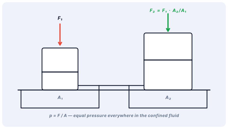
Hydraulics transmits force and motion through a confined, nearly incompressible fluid — usually mineral oil. The whole technology rests on Pascal's law (1653): pressure applied to a confined fluid is transmitted undiminished in all directions and acts with equal force on equal areas, at right angles to them.
p = F / A → F = p · A
If pressure p acts on two pistons of different area, the forces are proportional to the areas. A hand pump of 1 cm² pushing on 100 bar (10 MPa) produces 1 kN; the same pressure on a 100 cm² press plunger produces 100 kN ≈ 10 tonnes of force. That is the hydraulic lever — but energy is conserved: the small piston moves 100× further than the large one.
Units you will use constantly
Pressure: 1 bar = 0.1 MPa = 10⁵ Pa ≈ 14.5 psi. Mobile hydraulics typically 160–350 bar.
Try it in the Hydraulic Studio: put a pressure gauge on the piston side of a lifting cylinder and watch p rise exactly to p = (load force) / (piston area) before the cylinder starts to move.
hydraulicsbeginner✓ read
Pumps, displacement and flow rate
How pumps create flow (not pressure!), displacement volume, and why pressure only appears against resistance.
≈ 6 min read
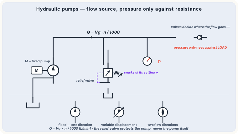
A hydraulic pump converts mechanical rotation into flow. The key spec is the displacement volume Vg (cm³/rev) — the volume pushed per revolution:
Q (l/min) = Vg (cm³/rev) × n (rpm) × ηvol / 1000
Pumps produce flow — resistance produces pressure
The pump does not "make" 200 bar. It pushes oil; pressure rises only because the flow meets resistance (a load, a restriction). With no resistance the outlet stays near zero. This is why every system needs a pressure relief valve: with the cylinder at its end stop, flow has nowhere to go and pressure would rise until something breaks — the relief opens and returns oil to tank.
Vane pumps — quiet, medium pressure; often variable displacement.
Axial piston pumps — high pressure (≤ 450 bar), variable displacement, pressure compensation and load-sensing control.
In the Studio, the power pack combines motor + pump + relief + tank. The pump flow (l/min) drives every speed calculation in the simulation.
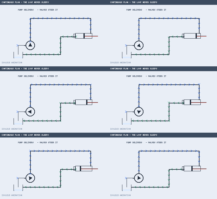
In motion: the pump keeps the loop alive — valves steer where Q goes.
hydraulicsbeginner✓ read
Cylinders: force, speed and area ratio
Push and pull forces, extension speed from flow, the annulus area effect and regenerative (differential) circuits.
≈ 7 min read
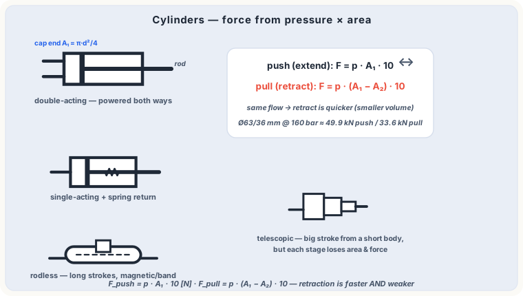
A double-acting cylinder converts pressure back into linear force. Two sides, two areas: the full piston area AK and the much smaller annulus AR on the rod side.
Fout = p · AK | Fin = p · AR v = Q / A
Worked example
Piston Ø 80 mm, rod Ø 45 mm → AK = 50.3 cm², AR = 34.4 cm². At 160 bar: push force ≈ 80.4 kN, pull force ≈ 55 kN. Feeding 40 l/min: extend speed ≈ 0.13 m/s, retract ≈ 0.19 m/s — the cylinder retracts faster on the same flow because the annulus is smaller.
Regenerative (differential) circuit
Connect P to the cap end and the rod side simultaneously: oil from the rod side joins the pump flow into the cap end. The result is a much faster extension at reduced force — perfect for rapid approach before a working stroke. The Studio's intermediate examples include this circuit with electric changeover.
Cylinder cushioning slows the piston over the last ~20 mm by throttling the outflow — it protects the end caps from repeated impact at speed.
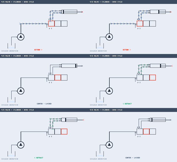
In motion: one full work cycle — extend, centre lock, retract.
hydraulicsintermediate✓ read
Pressure control: relief, reducing, sequence
The three classic pressure valves — what each one protects, regulates or triggers, and how to tell their ISO symbols apart.
≈ 7 min read
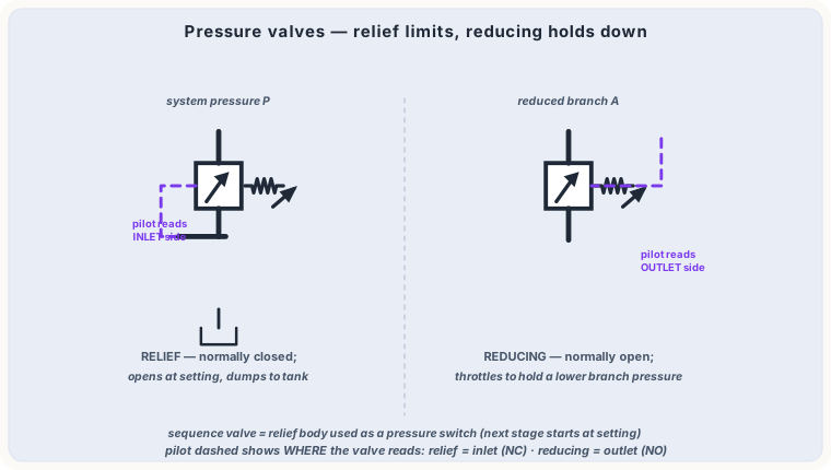
Pressure valves all compare line pressure with an adjustable spring, but they answer three different questions.
Relief valve — "how high may it go?"
Normally closed, piloted from its inlet, opens to tank at the setting. It limits maximum system pressure and protects the pump. It does not regulate during operation — it just caps peaks (and dumps all pump flow at setting at end of stroke).
Pressure reducing valve — "how low must it stay?"
Normally open, piloted from its outlet: it starts closing when outlet pressure exceeds the setting, holding the downstream branch at reduced pressure. Used when one branch (e.g. a clamp) needs less force than the main system.
Sequence valve — "when may the next step start?"
Normally closed, piloted from inlet like a relief, but its outlet feeds another actuator instead of tank: step 2 starts only after step 1 reached the pressure that proves it finished (e.g. clamp → drill). It needs an external drain because its outlet is pressurised.
Simulate a sequence in the Studio: put a sequence valve before a second cylinder and watch the messages report cylinder 1 completing before cylinder 2 moves.
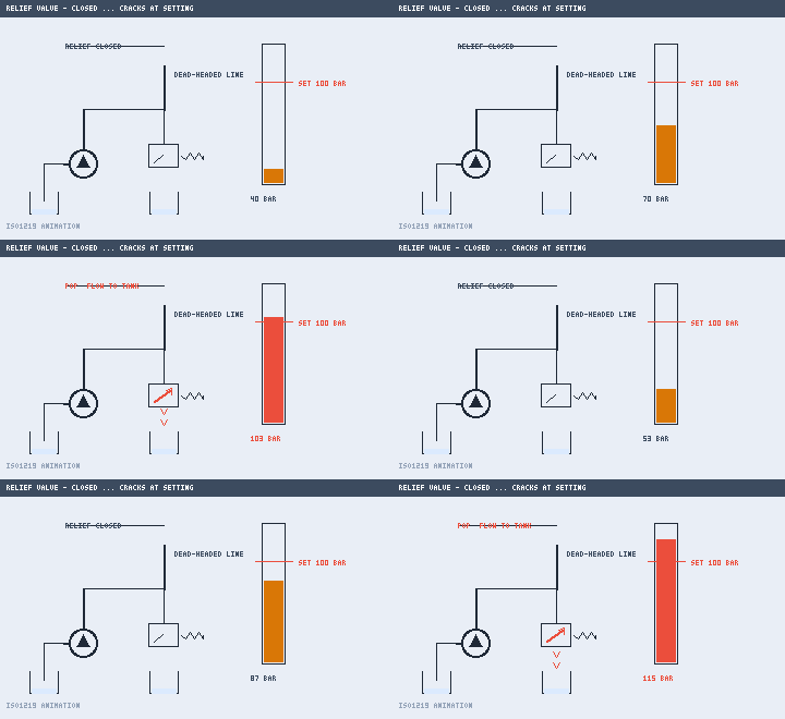
In motion: pressure climbs until the relief cracks at its setting and dumps to tank.
hydraulicsintermediate✓ read
Directional valves & ISO 1219 symbols
Positions and ways (4/3, 4/2…), center spool types, actuation methods — and how the square-box ISO symbol encodes all of it.
≈ 8 min read
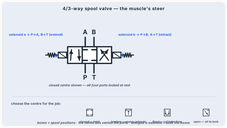
A directional control valve (DCV) routes flow between ports. "4/3" means 4 ports × 3 positions. Ports: P (pressure), T (tank), A and B (actuator). Each square box shows one spool position with the internal connections drawn inside it.
Reading the symbol
Arrows inside a box = open flow paths; ⟂-ends = blocked ports in that position.
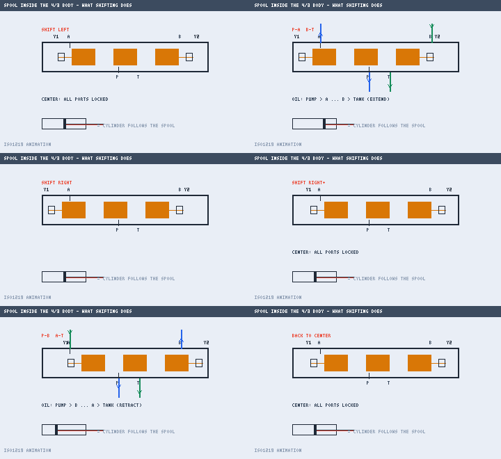
When a solenoid is energised, the adjacent box becomes active — in the Studio the boxes literally slide across the ports during simulation.
Springs push the spool back (spring-return) or hold it centered (spring-centered).
Center positions (4/3 valves)
Closed center — all ports blocked: cylinder locks, pump must unload through the relief.
Tandem center (P→T) — pump idles unloaded while the cylinder stays locked. Energy saving.
Float center (A,B→T) — the actuator can be pushed freely (e.g. for manual positioning).
Actuation
Manual lever, push-button, roller (limit), spring, pneumatic pilot (triangle) and solenoid (rectangle with diagonal). Detents hold a manually shifted spool.
In motion: solenoids pull the spool across — ports swap P→A / B→T, then reverse.
hydraulicsadvanced✓ read
Flow control: meter-in, meter-out, PC valves
Controlling actuator speed with throttle valves — why placement matters, and when you need pressure compensation.
≈ 7 min read
Speed follows v = Q/A, so controlling flow controls speed. A simple throttle (needle valve) creates a pressure drop that depends on flow — hence its control is load dependent.
Meter-in vs meter-out
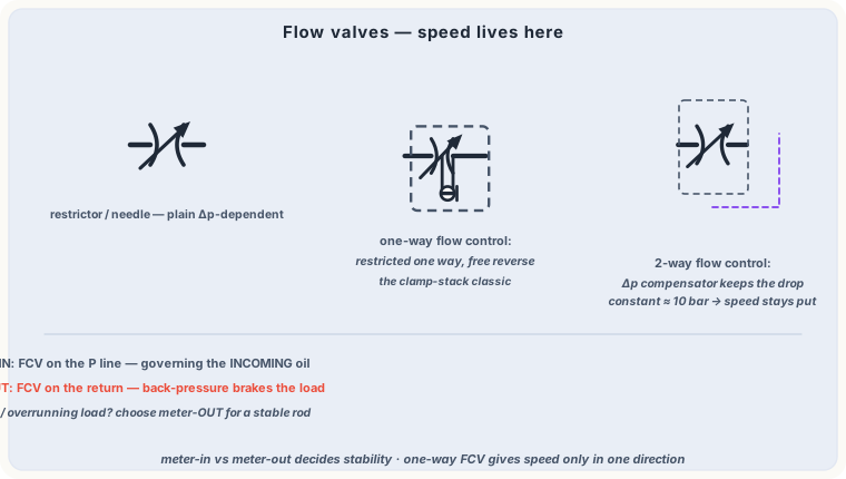
Meter-in: throttle on the supply line. Simple, but with overrunning (pulling) loads the cylinder can run away — pressure collapses on the cap side.
Meter-out: throttle on the return line. The trapped oil on the rod side is pressurised by the load, giving stiffness and safe control of lowering/overrunning loads. The rule of thumb for vertical cylinders: control the outflow.
Check-valve bypass
Pair the throttle with an antiparallel check valve and you get one-way speed control: throttled extend, free retract (or vice versa) — the classic "Flow control valve with bypass" in the Studio palette.
Pressure-compensated (2-way) flow control
A compensator spool keeps a constant Δp (≈ 5–10 bar) across the adjustable orifice, so the set flow stays constant regardless of load. That is what guarantees identical speeds under varying force.
hydraulicsadvanced✓ read
Oil, filtration and thermal management
Viscosity and ISO VG, why 70 % of failures are dirt, cleanliness codes, and when a system needs a cooler.
≈ 6 min read
The fluid is a machine element
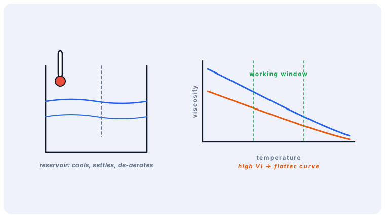
Hydraulic oil transfers power, lubricates, seals gaps and carries heat away. Its most important property is viscosity, specified as ISO VG (mm²/s at 40 °C). Typical choice: VG 32–46; too thin → internal leakage and wear, too thick → cavitation and sluggish response at cold start.
Contamination — failure driver #1
Roughly 70–80 % of hydraulic failures trace back to contaminated oil. Cleanliness is coded by ISO 4406 (e.g. 19/17/14 particles >4/6/14 µm). Servo valves need ~2 classes cleaner than gear pumps. Filters are rated by the β-ratio: β10 = 200 means 99.5 % of 10 µm particles are captured.
Heat
Every pressure drop becomes heat: Ploss = Δp × Q / 600 kW. Relief-valve throttling at end of stroke is a frequent heater. If the tank cannot dissipate it (~0.6–1.0 kW per 100 l tank by natural convection), add a return-line cooler — in the Studio you can place oil coolers and a heater with temperature sensors.
Watch the simulated oil temperature in the Hydraulic Studio metrics as relief flow heats the tank over time.
pneumaticsbeginner✓ read
Compressed air: production and properties
Why pneumatics, compressor types, the bar/psi units, and why dry air matters (pressure dew point).
≈ 6 min read
Pneumatics uses compressed air — clean, fast, overload-safe and available everywhere in a factory. Typical working pressure is 6 bar. Air is compressible: that makes pneumatics springy (great for clamping and end-stop cushioning) but less precise than hydraulics for exact positioning.
Production chain
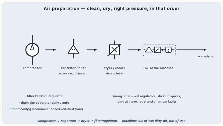
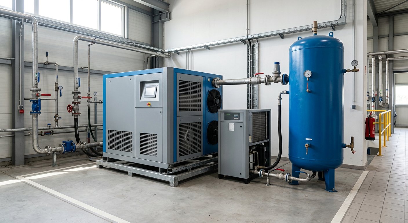
Compressor: piston (small/intermittent) or screw (continuous, quiet). It draws in free air and compresses ~7:1.
Cooler & dryer: hot compressed air holds water vapour; cooling makes it condense. A refrigerated dryer brings the pressure dew point to +3 °C; adsorption dryers reach −40 °C for instruments and outdoors lines.
Receiver: the tank levels consumption peaks and lets the compressor cycle less often.
Units
1 bar = 100 kPa ≈ 14.5 psi | "NL/min" = normal litres per minute (free air)
A pressure gauge in pneumatics shows relative pressure (bar gauge); absolute pressure = gauge + 1.013 bar — that matters for air consumption calculations.
pneumaticsbeginner✓ read
Air preparation: the FRL service unit
Filter, regulator, lubricator — what each stage does, ISO 8573-1 air classes, and condensate handling.
≈ 6 min read
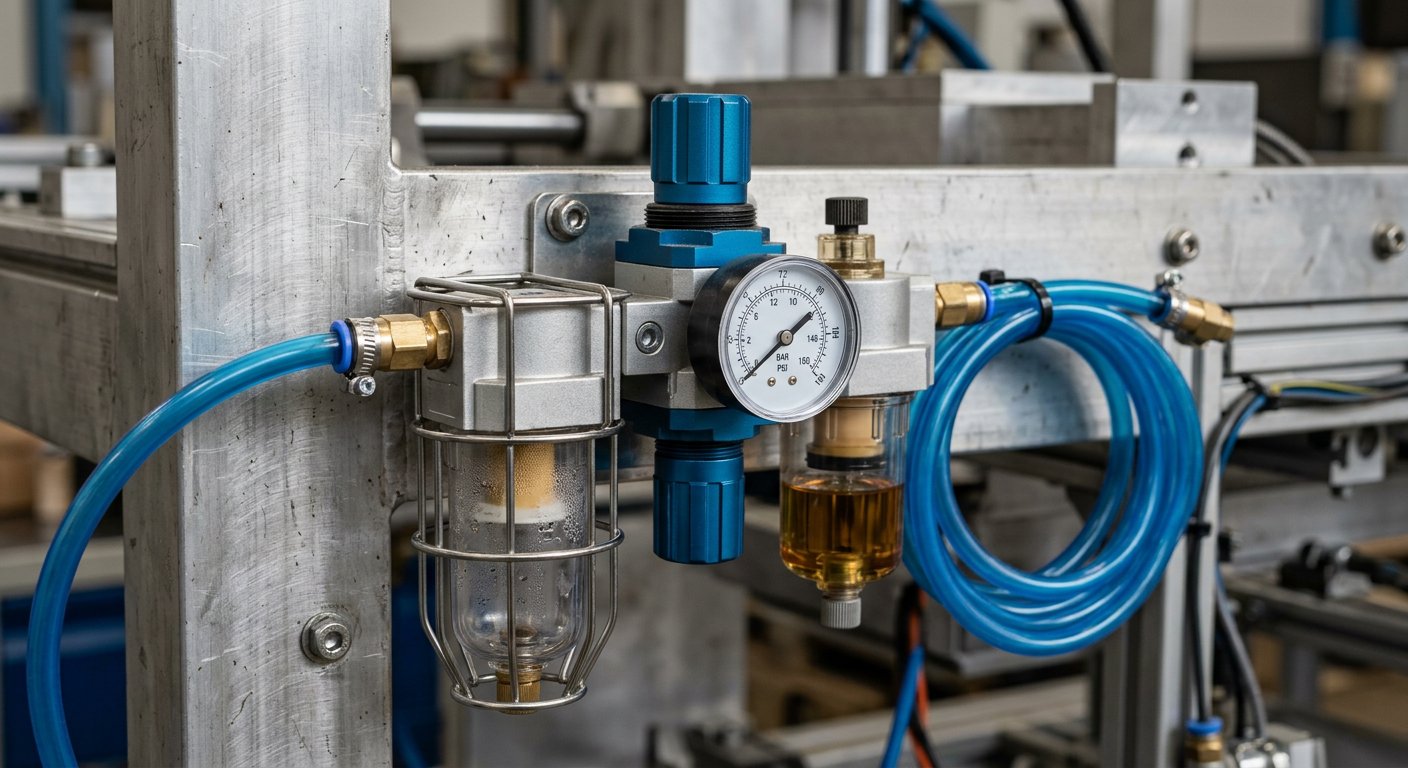
Between network and machine sits the service unit — in the Studio it is one symbol combining all stages (insert it with "Service unit").
F — Filter
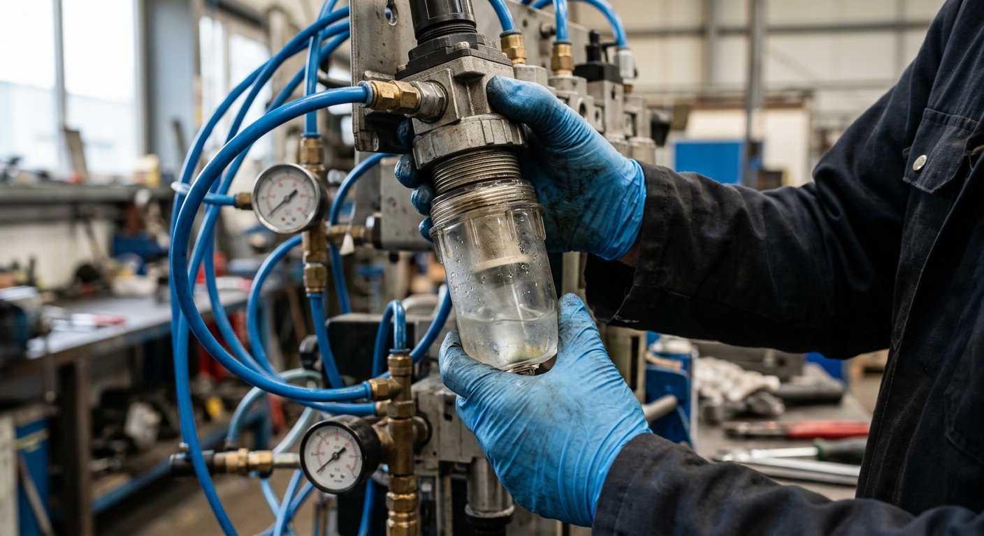
Separates water droplets and particles (typ. 5–40 µm) in a cyclone chamber; condensate collects in the bowl and drains manually or automatically. Air quality classes follow ISO 8573-1 (particles / dew point / oil), e.g. class 7.4.4 for standard shop air.
R — Pressure regulator
A diaphragm poppet holds the secondary pressure constant even when the primary side fluctuates, and vents overpressure (relieving type). This is the knob the operator sets — usually 6 bar.
L — Lubricator
Adds a fine oil mist for old-style cylinders and tools. Modern machinery is designed lubrication-free (special seals and materials); if a lubricator is installed, it must never run dry — once oiled, always oiled.
Order matters: filter first, then regulator, then (optionally) lubricator — never reversed. In the Studio the service unit already wires filter → regulator correctly.
pneumaticsbeginner✓ read
Pneumatic cylinders and speed control
Single vs double acting, force at 6 bar, cushioning — and why air exhaust throttling is the standard speed control.
≈ 6 min read
Single-acting (SA)
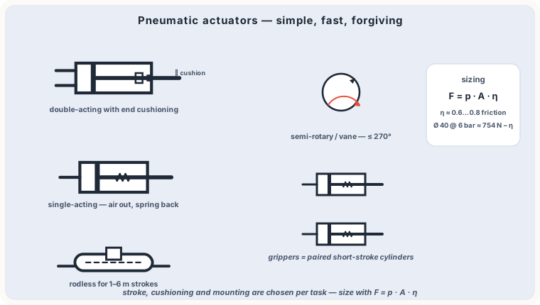
One port; air extends the piston and a return spring retracts it when vented. Used for short strokes, clamps, ejectors. Force is reduced by the spring.
Double-acting (DA)
Air drives both directions. Force at 6 bar (0.6 MPa):
F = p · A → Ø 50 mm cylinder: F ≈ 6 · 10⁵ · 1.96 · 10⁻³ ≈ 1180 N
End-position cushioning throttles the exhaust over the last millimetres so heavy loads do not slam into the end caps.
Speed control: throttle the exhaust
With compressible air, meter-in throttling causes stick-slip: the piston hesitates, pressure builds, then it jumps. The standard is meter-out (exhaust-air) flow control at each cylinder port — the trapped air cushions and stiffens the motion. A quick-exhaust valve does the opposite: it vents directly at the cylinder for maximum return speed.
Beyond the classic cylinder
When space or stroke length rules the design: rodless cylinders (magnetic or band coupling between piston and outer carriage — stroke equals the unit length, not twice it), compact and short-stroke cylinders, guided drives, rotary actuators (vane or rack-and-pinion) for swivelling, and bellows/actuated grippers. All follow the same force formula on their effective area.
In the Pneumatic Studio, each flow control with bypass acts as the exhaust throttle; simulate and watch the cylinder speed follow your screw setting.
pneumaticsintermediate✓ read
Pneumatic valves: 3/2, 5/2, 5/3 & piloting
Port numbering (1, 2, 3, 4, 5 — ISO 5599), monostable vs bistable, air-piloted control and center functions.
≈ 7 min read
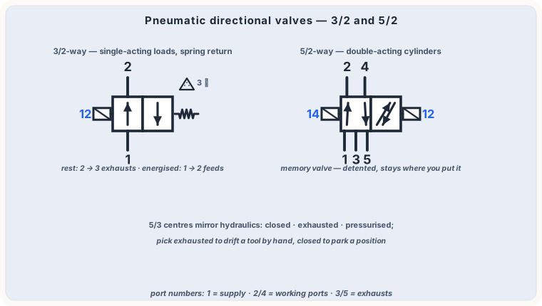
Pneumatic valve ports follow ISO 5599: 1 = supply, 2 & 4 = working lines, 3 & 5 = exhausts, 12/14 = pilot lines. So a 5/2 valve has 5 ports and 2 positions.
3/2 valve — the basic switch
Controls single-acting cylinders or acts as a signal element: NC (normally closed, supply blocked at rest) or NO. Push-button, roller lever (limit switch), or air-pilot actuation.
5/2 valve — the cylinder driver
Monostable (single pilot + spring return): returns to rest when the pilot disappears — predictable fail state.
Bistable (double pilot): a pulse switches it and it stays (memory) until the opposite pilot arrives — ideal for sequence control.
5/3 center functions
Mid position with all ports closed (holds cylinder), both chambers exhausted (free movement), or both pressurised (approximate stop in position).
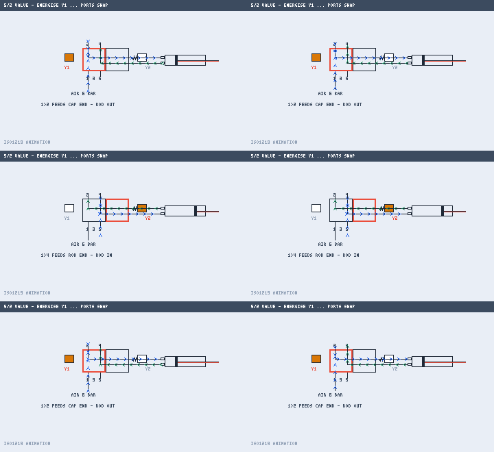
Watch the Pneumatic Studio: during simulation the 5/2 boxes slide to the energized side exactly like the real spool shifts.
In motion: energise Y1 vs Y2 and watch the 5/2 swap the port paths.
pneumaticsadvanced✓ read
Logic elements and sequence circuits
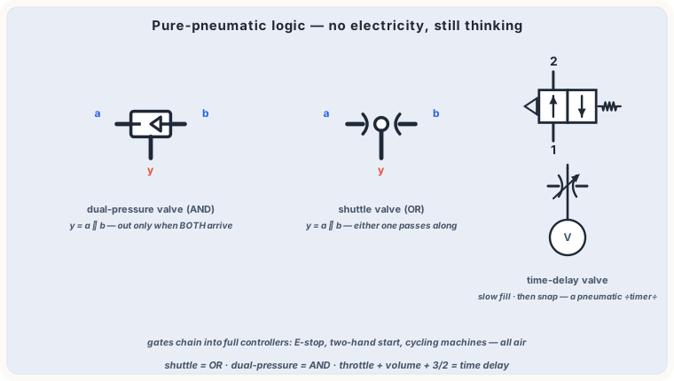
AND (two-pressure valve), OR (shuttle valve), time delays — and how classic sequences like A+ B+ B− A− are built.
≈ 8 min read
OR — shuttle valve
Two inlets, one outlet; an internal ball connects the pressurised inlet to the outlet. Either push-button OR the other starts the cylinder (e.g. control from two positions).
AND — two-pressure valve
Output only when both inlets are pressurised (it passes the lower pressure). Used for two-hand safety/start conditions: start only when button AND end position are present.
Time delay valve
A 3/2 valve + flow control + small air reservoir: after the pilot arrives, the chamber fills through the throttle until switching pressure is reached — an adjustable pneumatic timer (0…30 s typical).
Sequence example: A+ B+ B− A−
Cylinder A extends (clamp), then B extends (work), B retracts, A retracts. Realised with roller valves at each end position reporting "step done" to the next valve, or with a cascade/stepper module that only enables the active step — eliminating trapped opposing signals, the classic trap in pneumatic sequencing.
Recreate this in the Studio's advanced examples — the messages panel reports every switch event as the sequence runs.
pneumaticsadvanced✓ read
Air consumption, sizing and leakage
Free-air consumption of cylinders, Cv/Kv sizing of valves, tube sizing, and the hidden cost of leaks.
≈ 7 min read
How much air does a cylinder use?
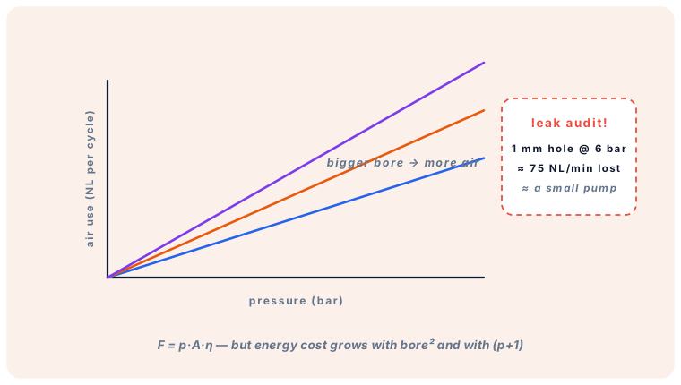
Per stroke, the cylinder volume is filled from (pgauge+1) atmospheres down to 1 — consumption in normal litres:
VNL = A · s · (pabs) ≈ A · s · (pbar,g + 1)
Example: Ø 63 mm × 400 mm stroke DA at 6 bar: ≈ 1.25 l chamber × 7 ≈ 8.7 NL per extend, plus rod-side ~7.9 NL — about 16 NL per full cycle. Multiply by cycles/min for compressor sizing.
Sizing valves and tubing
Valve flow capacity is given as nominal flow (NL/min) or C V / K V; undersized valves starve the cylinder and slow it down. Main lines are typically sized for ≤ 6–8 m/s mean velocity, drops and pressure loss ≤ 0.3 bar to the farthest consumer.
Leaks are expensive
A single 1 mm hole at 6 bar loses ≈ 75 NL/min — continuously, even when machines are off. At typical electricity prices that is several hundred euros per year per hole. Leak audits pay for themselves in weeks.
generalbeginner✓ read
Reading ISO 1219-1 circuit symbols
The grammar of fluid-power schematics: boxes, circles, triangles, solid vs dashed lines, and composite symbols.
≈ 6 min read
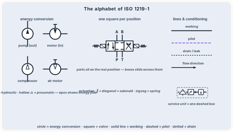
ISO 1219-1 defines the graphic symbols for fluid-power circuits — the "alphabet" every schematic in the RGZ studios follows.
Basic shapes
Circle — energy conversion: pump, motor, compressor, measuring device. A filled triangle inside shows flow direction (out = pump, in = motor).
Square/rectangle — valves. One square per position; arrows inside = open paths, ⟂ ends = blocked.
A crossing dot means connected; a small arc (or nothing) means not connected.
Energy & control
Triangles on the symbol edge mark flow direction of energy converters. Actuation glyphs attach to valve boxes: springs (zigzag), solenoids (rectangle with diagonal), manual, roller, pneumatic pilot (outline triangle), detents (notches).
Open the circuit library in either studio and read a schematic: every symbol you see — from power pack to sequence valve — follows these exact rules.
In motion: the same slide-the-boxes logic you just read symbol by symbol.
hydraulicsbeginner✓ read
Anatomy of a hydraulic power unit
Tank, motor, pump, coupling, relief and breather — how the component groups of a power pack work together and how the Studio models it.
≈ 7 min read
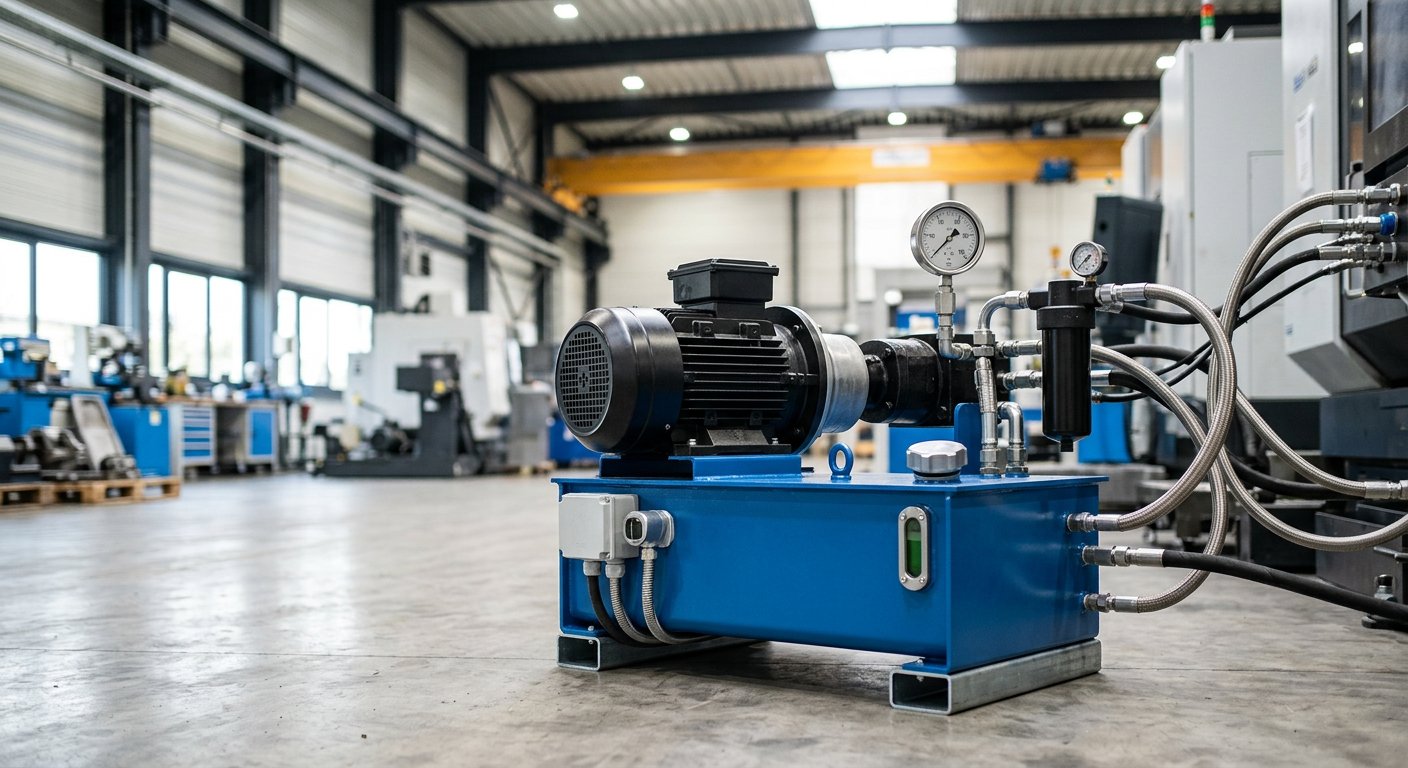
The hydraulic power unit (HPU) is the heart of every system. In the Studio you place it with one click ("Power pack"), but inside that symbol lives a complete component group — worth knowing part by part.
Component groups
Tank (reservoir) — stores oil, lets it cool and de-aerate, and settles dirt and water. Rules of thumb: 2–4× pump l/min for industrial units. Includes the breather filter, level gauge, and baffle plate separating suction and return zones.
Electric motor + pump — typically a 4-pole motor (≈ 1450 rpm at 50 Hz) driving a gear, vane or piston pump through a bellhousing and flexible coupling.
Pressure relief valve — mounted right after the pump, returns to tank; sets the maximum system pressure.
Suction line — generously sized (0.5–1.5 m/s) with a strainer; starving the suction line is the #1 cause of cavitation.
Optional: return-line filter and oil cooler, accumulator station, level/temperature switches.
In the Studio, the power pack exposes P (pressure) and T (tank) ports plus its pump flow, relief setting and motor power — everything the simulation needs to compute live pressure, flow and temperature.
hydraulicsintermediate✓ read
Hydraulic accumulators: energy storage
Bladder, piston and diaphragm types, the pre-charge rule, and the four classic jobs of an accumulator station.
≈ 6 min read
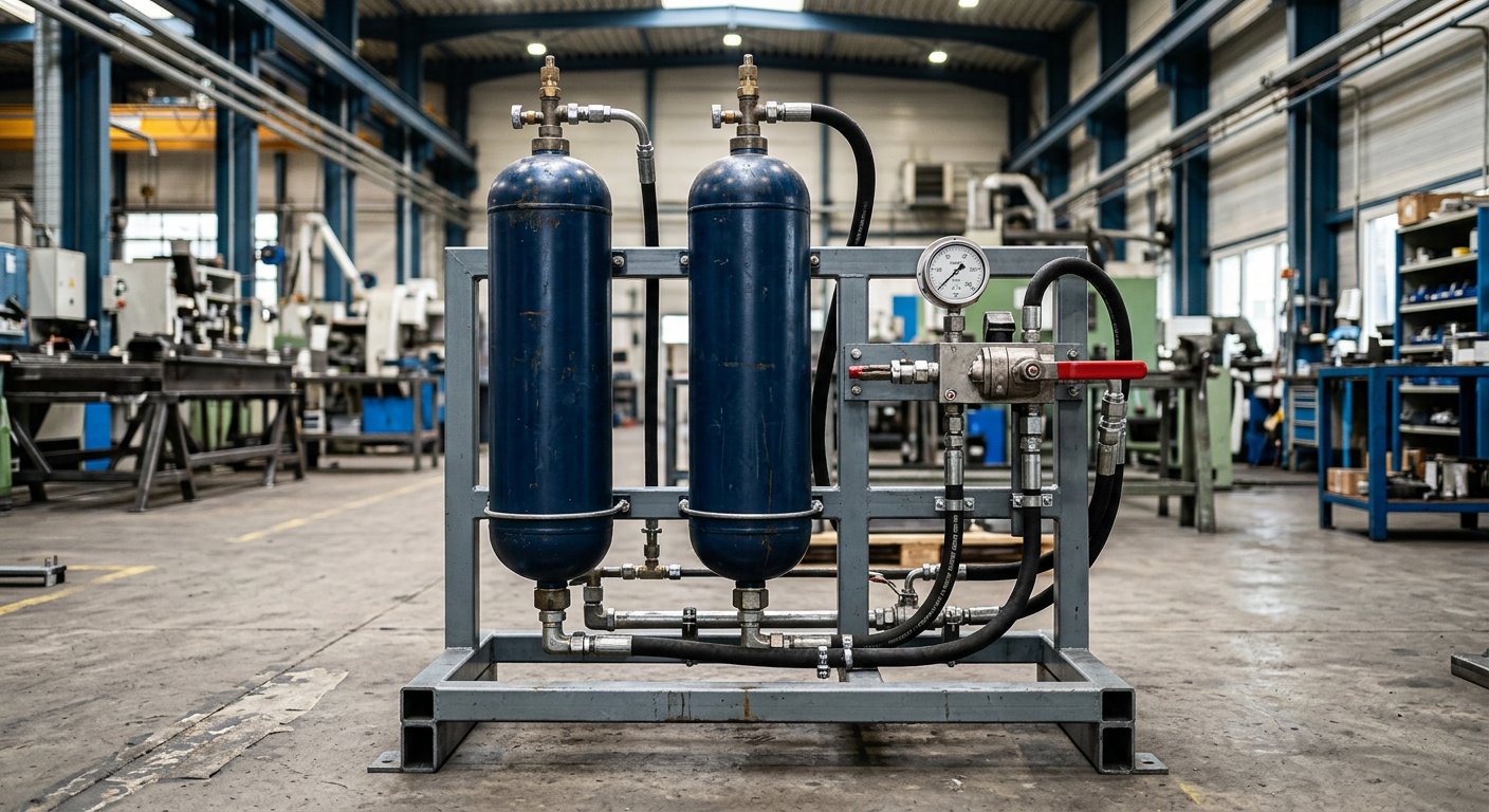
A hydro-pneumatic accumulator stores oil against compressed nitrogen. Types: bladder (fast response, most common), piston (large volumes, high pressure), diaphragm (small sizes).
Pre-charge pressure p₀
The nitrogen pre-charge defines the working window. Filling must never drop below p₀ (bladder damage) and the system must never compress the gas to its limit. Common rule: p₀ ≈ 0.6–0.8× minimum working pressure (0.9× for damping tasks). Usable volume follows the gas law:
Vusable = V₀ · p₀ · ( 1/p₁ − 1/p₂ ) (isothermal)
The four classic jobs
Energy storage — cover peak flows so the pump can be sized smaller.
Emergency reserve — complete a safety movement after power/pump failure.
Pulsation and shock damping — absorb pump ripple and water hammer.
Leakage compensation / clamping — hold pressure in a closed circuit against small leaks.
Safety: accumulators store pressure even with the machine off. Lock out and verify depressurisation on the gauge block before opening any line — a charged accumulator is a real hazard.
hydraulicsintermediate✓ read
Cavitation, aeration and micro-dieseling
Why pumps scream and die young: vapor bubbles at the suction, implosion damage, and how to prevent them by design.
≈ 6 min read
Cavitation
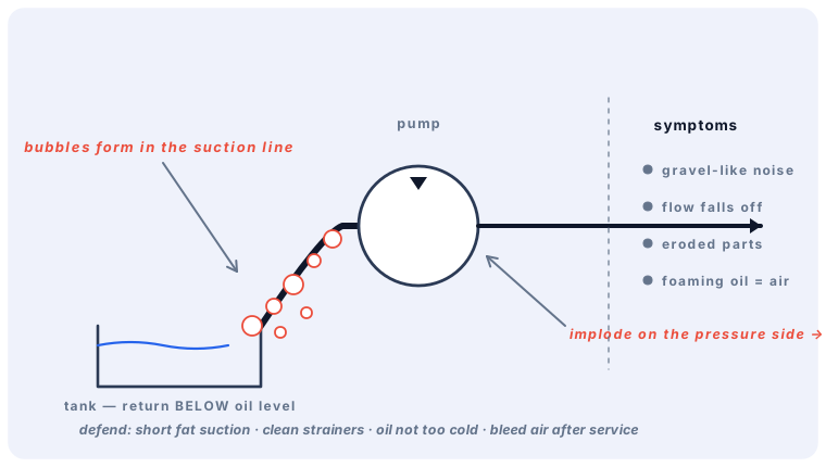
If absolute pressure in the suction line falls near the oil's vapor pressure, vapor bubbles form. Carried to the pressure side, they implode in microseconds, creating micro-jets up to ~1000 bar that erode nearby metal (pitting). Symptoms: the pump gets loud (gravel rattling), flow falls, and the suction elements wear fast.
Typical causes
Suction line too long / too narrow / clogged strainer (keep 0.5–1.5 m/s velocity).
Cold start with too-viscous oil; tank below the pump with too much lift.
Oil too hot → higher vapor pressure.
Aeration vs cavitation
Aeration = air entering (leaky suction fitting, foaming return above oil level). It makes oil spongy and can cause micro-dieseling: compressed air bubbles ignite the oil-air mixture locally like a diesel engine — scorching seals and degrading the oil.
Design defense: short, generous suction; pump below oil level where possible; return lines always below the surface; bleed air after commissioning; check strainers on schedule.
hydraulicsintermediate✓ read
Pressure drop in lines and fittings
Where the pressure goes: line friction, velocity classes for suction/pressure/return, and picking hose and tube diameters.
≈ 8 min read
Every restriction converts pressure to heat. Line losses follow Darcy–Weisbach:
Δp = λ · (L / d) · ρ v² / 2 with v = Q / A
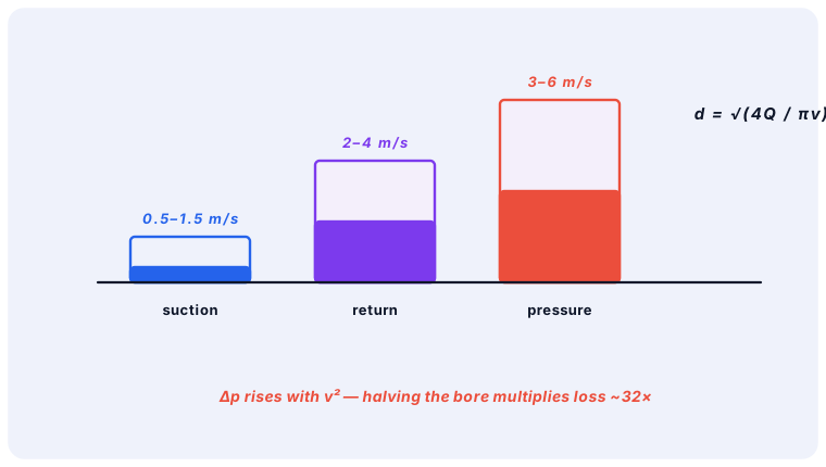
Note the brutal exponent: loss rises with velocity² — and halving the diameter multiplies the loss ~32×. Fittings, elbows, valves and filters add their own resistances (Σζ).
Velocity classes (rules of thumb)
Suction: 0.5 – 1.5 m/s (cavitation-safe)
Return: 2 – 4 m/s
Pressure lines: 3 – 6 m/s (up to ~100 bar), 5 – 7 m/s at higher pressure
Choosing hose bore
From the target velocity: d = √(4Q / πv). Example: 60 l/min in a pressure line at 5 m/s → d ≈ 16 mm inner bore — the next standard size up wins. Hoses also age faster at temperature peaks and must meet the pressure rating with a safety factor ≥ 4:1 against burst.
The Studio's pipe sizing tool computes inner diameter, velocity and Δp for each line in your schematic during simulation — watch red warnings when a line is undersized.
hydraulicsbeginner✓ read
Hose routing and piping practice
Minimum bend radius, torsion, slack, clamps and cleanliness — the installation rules that decide a hose assembly's lifetime.
≈ 6 min read
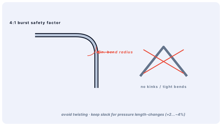
Most premature hose failures are installation failures. The rules come straight from EN 853/856 and manufacturer practice:
Routing rules
Respect minimum bend radius — bending tighter crushes the wire reinforcement; allow the radius printed on the hose layline.
Never torsion a hose — twist during installation or operation destroys it fast. Route so the flexing plane contains both fittings (compensate with elbows, not twist).
Add slack for pressure growth — hoses shorten up to 4 % under pressure; a dead-straight, tight hose rips its fittings out.
Clamp correctly — support long runs with proper clamps (vibration-safe), but never clamp at the bend.
Protect — against abrasion (sleeves/separation), heat sources, and sharp edges.
Cleanliness at assembly
Flush new pipes, cap open ends immediately, and clean hose assemblies after cutting/crimping — rubber and metal residue from assembly is a classic early-failure cause for valves and pumps downstream.
Use the layline as a sight line: one continuous printed line = no twist; a spiral layline = the hose is torsioned.
hydraulicsadvanced✓ read
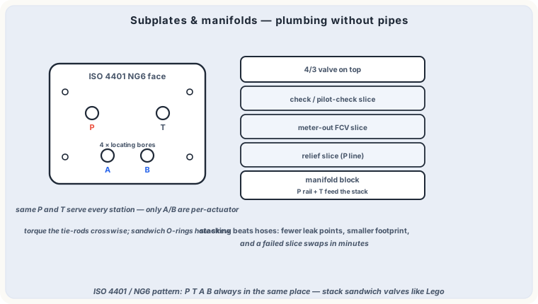
ISO 4401 patterns, stack & manifold design
NG6/NG10 porting patterns, subplates and sandwich valves — how industrial valve stations are physically assembled.
≈ 7 min read
Industrial DCVs bolt onto standardized interfaces defined by ISO 4401 (DIN 24340): size 03 = NG6 (¼"), 05 = NG10 (⅜"), 07 = NG16, 08 = NG25, 10 = NG32. The pattern fixes exactly where P, T, A, B (and X, Y, L) ports sit, with locating pin and bolt holes — so any brand's valve fits any pattern-correct plate.
Three ways to build a station
Subplates — one valve per plate, piped externally. Simple, flexible, but many fittings and leak points.
Sandwich (modular/stack) valves — same-pattern plates stacked between DCV and subplate: relief, throttle, check or reducing functions added with zero piping. Two valves are 8–14 bolts and one O-ring set.
Manifold blocks (HIC) — a drilled steel/aluminium block carrying many valves with internal galleries: few fittings, compact, clean. Design rules: keep galleries generous (low Δp!), avoid intersecting drillings, provide test points M16×2, and allow future expansion plugs.
In the Studio, the cartridge manifold/HIC boundary symbol lets you group screw-in and logic cartridge valves exactly like a real manifold — with the dash-dot enclosure line of ISO 1219.
hydraulicsintermediate✓ read
Selecting a hydraulic cylinder
Bore from force, check the load with reserve, then verify the piston rod against buckling on long strokes.
≈ 6 min read
Step 1 — Bore from the required force
A ≥ F / (p · ηhm) with ηhm ≈ 0.85–0.95
Round up to the next ISO bore (25, 32, 40, 50, 63, 80, 100, 125, 160 mm…). Then check the retraction force too when it drives the load. Speeds follow from flow: v = Q/A — consider whether the annulus-side retraction speed suits the process.
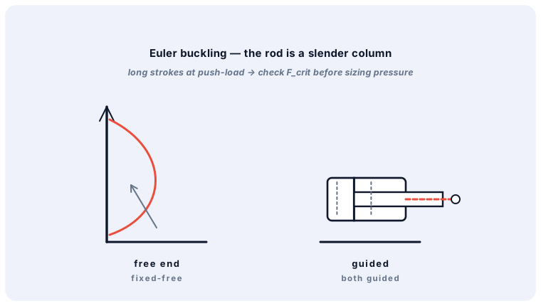
Step 2 — Buckling (Euler) on push strokes
A long, slender piston rod in compression can buckle — the governing case for presses and lift cylinders with free stroke. Effective buckling length depends on the mounting (guided/fixed ends), and manufacturers publish permissible load vs. stroke tables per rod diameter. Reduce the risk with: a thicker rod, guides/trunnion or clevis mounting nearer the load line, or reduced pressure.
Step 3 — Details that matter
Cushioning for kinetic energy at end of stroke; stop tubes for long strokes and side loads.
Seal selection vs temperature, speed and fluid.
Mounting style: avoid side loads on the rod (self-aligning couplings).
In the Studio, the cylinder inspector computes diameter, velocity and buckling checks live from your bore, stroke and mounting selection.
hydraulicsadvanced✓ read
Systematic hydraulic troubleshooting
A field-proven sequence: pressure first, then flow — plus how to find internal leakage and test cylinders for drift.
≈ 8 min read
The golden order: pressure first, then flow
Measure pressure at the pump outlet against relief setting. No pressure → check the prime mover, coupling, pump priming, relief stuck open.
Measure flow (or judge by actuator speed). Pressure OK but slow → pump worn, suction starved, or something bypassing.
Localize internal leakage: with the relief closed-end test (deadhead a cylinder; flow over relief should be pump flow if valves seal) — rising temperature over a valve or cylinder seals often reveals the leak.
Cylinder-specific checks
Drift test: load the cylinder, close both ports; external creep = seals/piston leak (feel for heat on the barrel).
Jerky motion → air in oil, sticky seals, or meter-in control on an overrunning load.
Rod seal leak → inspect rod surface for scoring first; a new seal on a damaged rod fails in days.
Instrument smart
Permanent test points (M16×2) at pump, relief, valve P/A/B make a 2-minute pressure reading possible without spilled oil. The Studio's test-point and gauge components mirror exactly that practice.
Write down the machine's healthy values (pressures, cycle times, temperatures). "Different from the logbook" is the fastest diagnostic signal that exists.
hydraulicsadvanced✓ read
Proportional valves & amplifier basics
How proportional spools differ from on/off valves, and the amplifier parameters gain, ramp, deadband and dither.
≈ 8 min read
On/off valves know two states; proportional valves position the spool continuously against a spring in proportion to the command current (typ. 4–20 mA or 0–10 V), metering flow (and thus direction and speed) in one valve. Servo valves go further: nozzle-flapper or jet-pipe pilot stages with micron-grade spools — maximum dynamics, but they demand very clean oil.
Amplifier parameters you'll meet on the card
Gain — maps command voltage to output current; sets full flow at full command.
Ramp (up/down) — slews the command to eliminate pressure shocks: soft start/stop of heavy cylinders.
Deadband / deadzone — the overlap region near zero; compensated to get faster response around center.
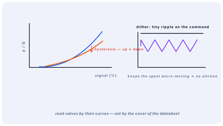
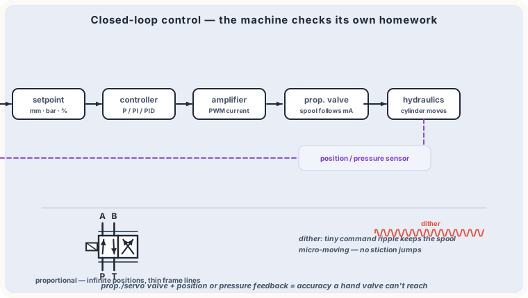
Dither — small high-frequency overlay (e.g. 100–200 Hz) that keeps the spool micro-moving, killing static friction (hysteresis).
Enable, wire-break detection, and LVDT feedback for closed spool-position loops.
Simulate a proportional axis in the Studio: amplifier, setpoint potentiometer and ramp generator components model command shaping, while the valve's spool slides progressively during simulation.
hydraulicsadvanced✓ read
Oil properties, additives & fire-resistant fluids
What a hydraulic fluid must do, how additives deliver it, and when to choose HFA/HFC/HFD fire-resistant fluids.
≈ 7 min read
The job description of a hydraulic oil
Transmit power with minimal compressibility and foaming.
Lubricate pumps/valves under mixed-film conditions (AW/EP additives form protective layers).
Keep viscosity stable: high viscosity index (VI) = less thinning when hot; typical HVLP oils reach VI > 100.
Protect against oxidation (long life), corrosion, and separate from water (demulsibility).
Fire-resistant fluids (ISO 12922)
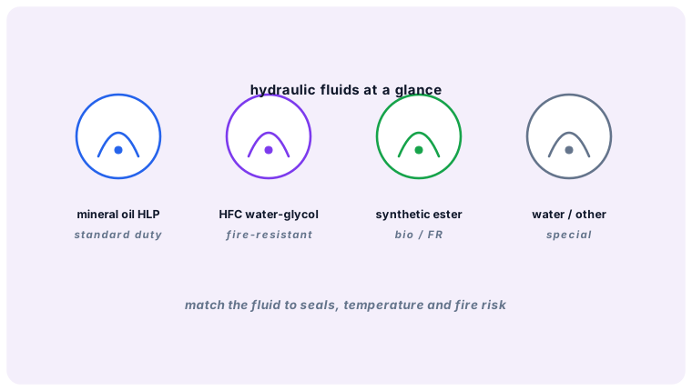
HFA-E/HFA-S — oil-in-water emulsions/solutions (~95 % water): steelworks and press lines near ignition sources; corrosion and narrow temperature window are the trade-offs.
HFC (water glycol) — good fire resistance with decent lubricity up to ~50–60 °C; watch seal and paint compatibility.
HFD (HFD-U esters / HFD-R phosphate ester) — lubricity near mineral oil; phosphate ester needs special seals (FPM/FKM, EPDM).
Never mix fluid types; changing types requires full flushing and filter/seal review.
Fire-resistant is not "no maintenance": HFC water content must be checked regularly, or viscosity and lubricity drift out of spec.
hydraulicsbeginner✓ read
Mobile vs industrial hydraulics
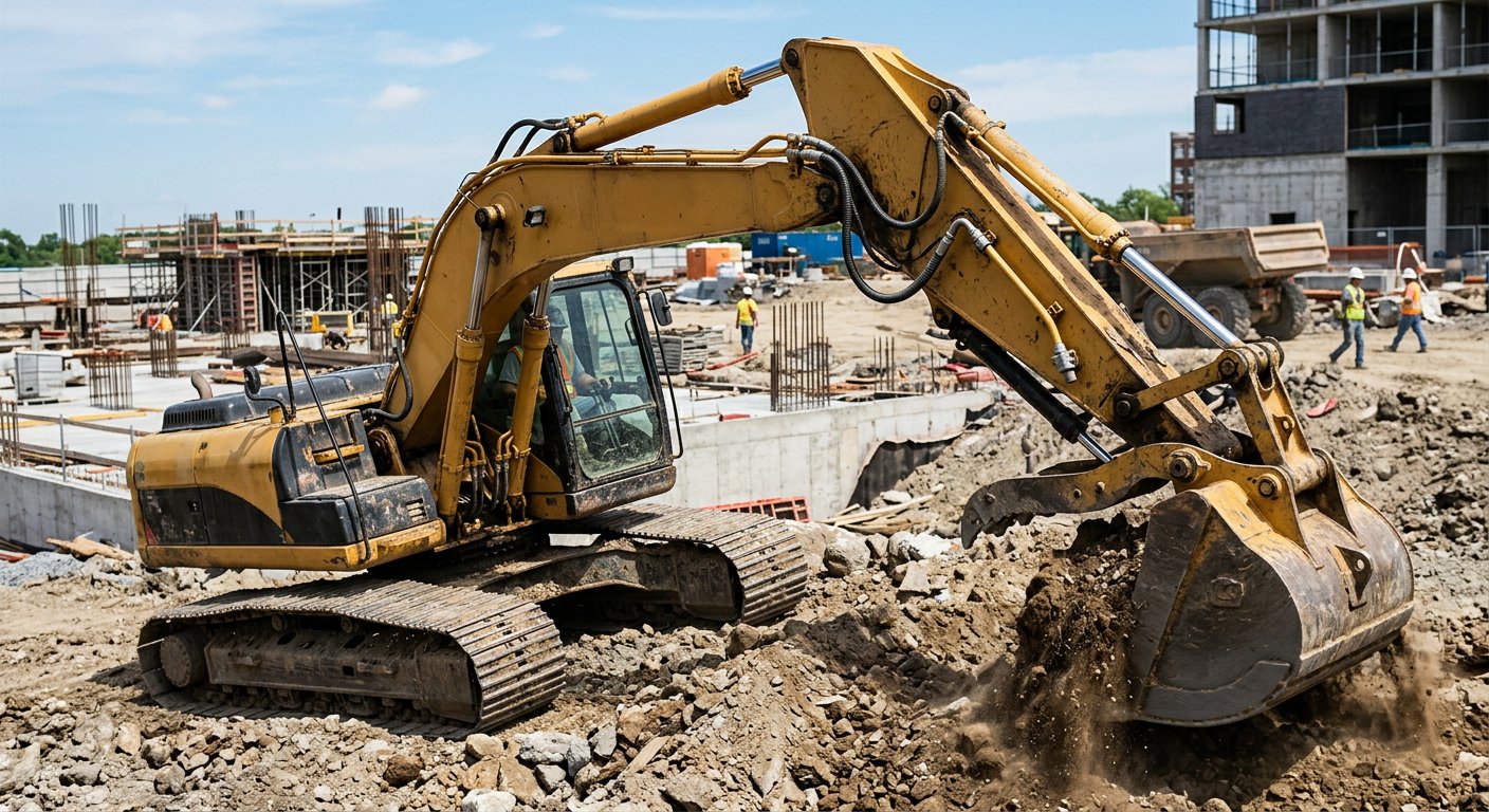
Excavator or injection molding machine? Why mobile systems look different: load-sensing, DCV blocks, and 24 V control.
≈ 5 min read
The physics is identical — but priorities differ sharply between a factory power unit and a mobile machine.
Industrial (stationary) hydraulics
Grid-powered, generous tanks, fixed speeds, quiet operation, long continuous duty.
Modular ISO 4401 valve stations, central hydraulic supply, 230/400 V solenoids, PLC control with relays/PLC outputs.
Mobile hydraulics
Engine-driven, weight- and space-critical, wide temperature/dirt/vibration exposure.
Load-sensing (LS) variable pumps: the pump follows demand, saving fuel; constant-pressure or power-regulated alternatives.
Monoblock/stacked mobile DCVs with manual levers or 12/24 V proportional actuation; often multiple functions simultaneously.
Fan-driven oil coolers are the norm; filtration works harder (dust ingress on rods!).
Same ISO 1219 symbols everywhere — a load-sensing pump in the Studio is just a variable pump with its compensator; practice reading both applications with the circuit library.
pneumaticsbeginner✓ read
Compressors and air receivers
Piston vs screw vs scroll, duty-cycle thinking, and how receivers buffer consumption and let the compressor rest.
≈ 6 min read
Compressor types
Piston (reciprocating) — economical for small/intermittent duty (workshop); watch the duty cycle (often 50–60 %) and oil carry-over unless oil-free.
Screw — continuous duty, efficient and quiet above ~10 m³/min; the industrial default, often with integrated dryer and VSD drive.
Scroll — compact, oil-free, quiet for labs and dental; limited capacity.
Discharge quality
Compressed air leaves hot and wet. An aftercooler drops most water immediately; a refrigerated dryer then sets the +3 °C pressure dew point typical for general industry (adsorption dryers for −20…−70 °C).
The receiver
Vrec ≈ ΔVconsumption · patm / Δpallowed
The tank buffers demand spikes so the compressor cycles less: a machine drawing 60 NL once per minute can run a much smaller compressor behind a correctly sized receiver. Keep the pressure band (load/unload settings) as narrow as hysteresis allows — every extra bar of band is wasted energy (~7 % more energy per bar).
The Pneumatic Studio's power unit combines compressor, dryer and receiver into one symbol like the hydraulic power pack — with a working pressure you set for the whole circuit.
pneumaticsintermediate✓ read
Vacuum technology & grippers
Ejectors, vacuum level vs flow, suction-cup holding force, and pneumatic grippers for handling.
≈ 6 min read
Vacuum from compressed air
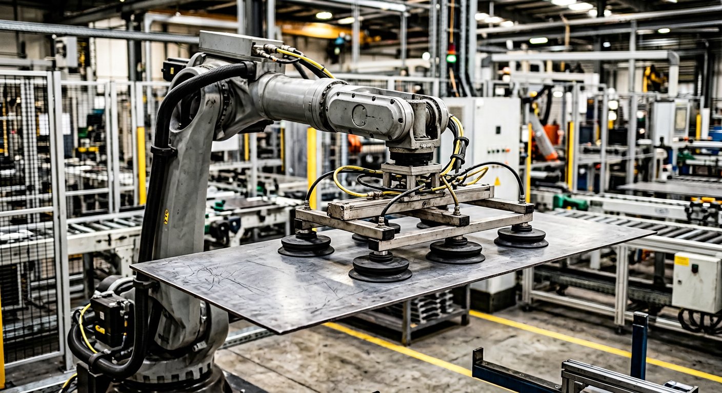
A venturi ejector accelerates supply air through a nozzle; the jet entrains air from the vacuum port and exhausts both through a silencer — simple, moving-part-free vacuum to about 85–95 % of atmospheric pressure. Multi-stage ejectors reach the same level with less air.
Suction cups: the physics
Fhold = Δp · Acup · (1/S) (S = safety factor 2–4)
Holding force comes from ambient pressure pushing the cup against the part — at −0.6 bar relative, a Ø 40 mm cup holds theoretically ≈ 75 N. For shear loads on vertical surfaces use double safety and bellows/oval cups on textures. Porous workpieces (cardboard, chipboard) need high-flow ejectors — leak rate, not vacuum level, governs.
Pneumatic grippers
Angular — hinged jaws, compact; closing force drops with jaw angle.
Rod-lock/clamp cylinders and rotary grippers for heavier fixtures.
Check cup sizing with the compressor-off emergency case: a vacuum switch gauges the level before lifting, and a non-return valve holds the cup if air fails.
pneumaticsintermediate✓ read
Electropneumatics: relays, sensors & PLC
Solenoids, reed switches, latching circuits and seal-in logic — the bridge from pure pneumatics to real machine control.
≈ 8 min read
Signal → solenoid → cylinder
An electrical push-button energizes the valve's solenoid coil (typically 24 V DC): the valve shifts, the cylinder moves. At the end position a reed switch on the barrel (or an inductive proximity sensor for parts) reports the position back — closing the loop for the next step.
Seal-in (self-holding) — the memory relay
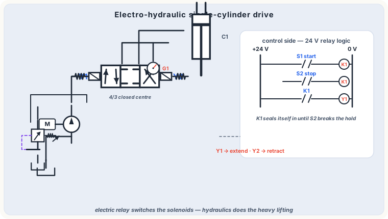
Detail you will use constantly: wire the relay's own NO contact in parallel with the start button. A pulse latches the relay ON ("seal-in"); the stop button (NC, in series) breaks it. That is exactly how the Studio's intermediate electropneumatic examples hold the cycle between start and stop.
Classic building blocks
AND/OR in relays = series/parallel contacts; in pneumatics = two-pressure/shuttle valves.
On-delay timer relays = the electrical counterpart of pneumatic time-delay valves.
Emergency stop (NC, safety category per ISO 13849) must cut power to the solenoids — and in critical cases, exhaust the air (soft-start/dump valve).
Combine both worlds in the Pneumatic Studio: buttons, relays, timer relays and PLC elements sit in the Control category and animate together with the air circuit during simulation.
pneumaticsbeginner✓ read
Pneumatic maintenance & troubleshooting
The three enemies — dirty air, moisture, leaks — and a quick diagnostic sequence for sluggish cylinders.
≈ 6 min read
The three enemies of pneumatics
Dirty air — wears seals and sticks valve spools; a 5 µm filter protects standard valves, lubricators (where present) must never run dry.
Moisture — condensate corrodes and washes grease from cylinders; drain filters and the dryer on schedule; tubes sloped to drain points.
Leaks — up to 25–30 % of generated air is lost in typical plants; hissing fittings, perished PU tubing, and leaky cylinder rod seals are the usual suspects. An ultrasonic detector finds inaudible leaks.
Sluggish cylinder? Quick sequence
Check supply pressure at the regulator (6 bar?) — a kinked tube or clogged filter upstream is common.
Listen at the valve exhaust — a choked silencer slows everything invisibly.
Check the flow-control (exhaust throttle) settings — they may simply be closed.
Verify the valve pilot reaches the coil (LED on the connector) — electrical before mechanical.
Disconnect and push the cylinder by hand to separate mechanical stickiness from pneumatics.
Track the service unit: a simple weekly glance at filter bowl + gauge prevents most pneumatic downtime. Pressure switch and gauge components in the Studio model precisely this instrumentation habit.
generalintermediate✓ read
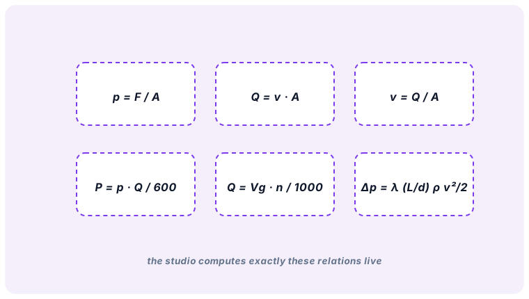
Formula cheat sheet: hydraulics & pneumatics
The twelve formulas that solve 90 % of fluid-power engineering tasks — from force and flow to power and air consumption.
A = π d² / 4 | Aring = π (d² − drod²) / 4 Fpush = p · A · ηhm | t = V / Q
Lines
Δp = λ (L/d) ρv²/2 | d = √( 4Q / πv )
Pneumatics
VNL ≈ A · s · (pbar,g + 1) per stroke Fcup = Δp · Acup / S
Accumulator
Vusable = V₀ p₀ (1/p₁ − 1/p₂)
Bookmark this lesson: it collects every formula the RGZ studios use internally for validation and simulation — the same numbers you read in the metrics panels.
generalbeginner✓ read
Electricity basics for fluid-power technicians
DC control circuits, Ohm's law, what a solenoid coil actually does with 24 V, and how to measure correctly with a multimeter.
≈ 7 min read
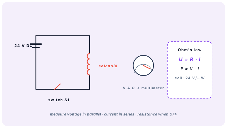
Every electro-hydraulic and electro-pneumatic machine is two systems in one: a power section (oil or air) and a signal section (electricity). The signal side almost always runs on 24 V DC — safe to touch, short-circuit tolerant and standard for industrial sensors and valves.
The simplest control circuit: supply → switch → solenoid → back to 0 V.
The three quantities
U = R · I | P = U · I
Voltage U (volts) pushes, current I (amperes) flows, resistance R (ohms) opposes. A typical valve coil: 24 V, 30 Ω → it draws 0.8 A and converts ≈ 19 W into the magnetic force that strokes the spool (plus heat — a coil is rated for 100 % duty and gets warm in service, that is normal).
What the coil does
Current through the winding builds a magnetic field that pulls an iron armature a few millimetres. That armature strokes the valve pilot or spool. No current → the return spring drives the valve home. This crisp ON/OFF behaviour is what makes solenoid valves the standard "muscle switch" of fluid power.
Measuring without guessing
Voltage — parallel to the load, circuit live (black probe 0 V rail, red at the coil terminal).
Current — the meter goes in series; measure at the coil supply wire.
Resistance / continuity — only with the circuit dead: a healthy 24 V coil reads 15–100 Ω, never 0 nor ∞.
Most "valve does not shift" faults are electrical: check the connector LED, then voltage at the coil pins — before touching a single wrench.
generalbeginner✓ read
Pushbuttons, switches and industrial sensors
NO vs NC contacts, reed switches on cylinders, inductive / capacitive / optical proximity sensors and electro-pneumatic pressure switches.
≈ 6 min read
Control starts with information: input devices delivered by people (pushbuttons, selector switches) and sensors delivered by the machine (positions, pressure, presence).
Mechanical contacts
A pushbutton has one of two resting states: NO (normally open — closes when pressed) and NC (normally closed — opens when pressed, used for STOP and safety chains). Contacts are numbered per standard: function digit first (1 = NC, 2 = NO), then the pole index — so 13–14 is the classic NO pair.
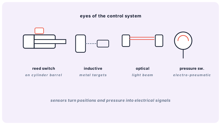
Four everyday sensor families of fluid-power automation.
Sensors you will meet
Reed switch — clamps on the cylinder barrel; the piston magnet closes the contact at its position. The standard end-position report on pneumatic cylinders (PNP outputs on modern models).
Inductive proximity — detects metal at 1–15 mm without contact; the workhorse for cylinder positions and parts presence.
Capacitive — also senses non-metals (water, oil level, granulate).
Optical — through-beam or reflex; long ranges, exact edges.
Pressure switch — converts an air/oil pressure threshold into a contact; e.g. "clamp pressure reached → drilling may start".
Output styles: PNP (switches +24 V to the input — European standard) and NPN (switches 0 V). Three wires: brown +24 V, blue 0 V, black signal.
A failing reed switch shows as a sequence that simply stops at one step — the system never "hears" the cylinder arrived. Check the sensor LED first.
generalintermediate✓ read
Relays, contactors and the self-latching rung
How a small signal switches a big load, contact numbering, pick-up vs drop-out delay, and the three-wire latching pattern every classic control is built from.
≈ 7 min read
A relay is an electrically operated switch: a small coil (24 V, <1 W) pulls an armature that moves isolated contacts. It separates control from load, multiplies one signal into many contacts, and stores information. A contactor is the same idea scaled for power loads (motors, pumps).
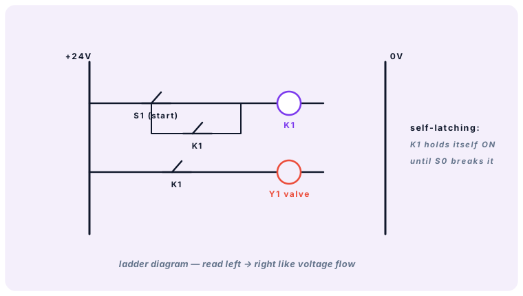
Self-latching: brief press on S1 energises K1; its own contact keeps K1 alive until S0 breaks the rung.
Self-latching (memory) in one rung
Put the relay's own NO contact in parallel with the START button. Press once → the coil energises and seals itself in through its contact. A NC STOP in series releases it. Exactly the same pattern appears everywhere: as ladder logic in a PLC, or as a double-solenoid valve's two coils (SET / RESET).
Reading relay data
Contacts numbered like switches: 13–14 (NO), 21–22 (NC), 31–32…; the coil is A1/A2.
Pick-up vs drop-out — a relay pulls in within ~10 ms and falls out when the coil drops below roughly 10 % of nominal; undervoltage makes contacts chatter.
Timing relays add on-delay / off-delay to the same housing — the electrical counterpart of the pneumatic time-delay valve.
Modern machines replace relay walls with a PLC, but the logic is identical: school yourself on relay ladders and PLC programs become trivial to read.
pneumaticsintermediate✓ read
Electro-pneumatics I: solenoid valve control
The 5/2 solenoid valve as the interface between electricity and air: direct vs control-side actuation, coil ratings, overrides and a complete press example.
≈ 8 min read
Gate between the worlds: the solenoid directional valve. Its coil moves a small pilot; the pilot air strokes the main spool (on larger valves) or the coil drives the spool directly (small 3/2, 5/2 valves).
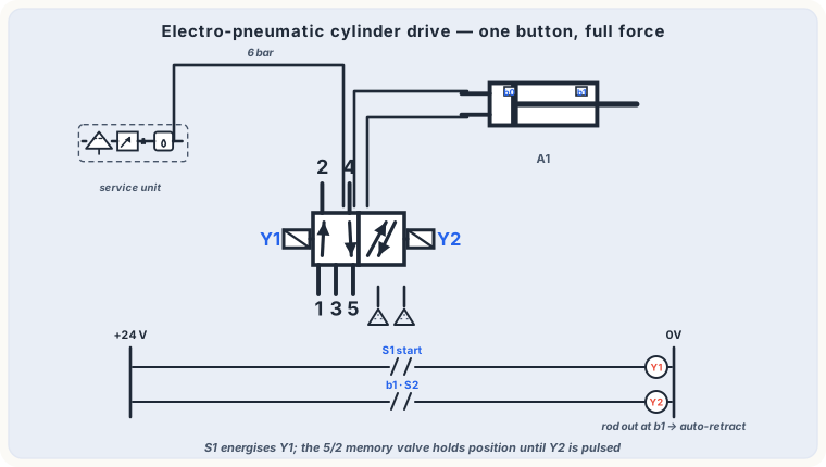
Pneumatic power section + electrical signal section of the same machine.
Two control philosophies
Direct — the pushbutton feeds the valve coil. One wire, immediate, but the button carries the coil current.
Via relay / PLC output — the button only informs the logic; a protected output drives the coil. This is how every real machine is built.
Choosing and reading a coil
Voltage: 24 V DC (standard), sometimes 110/230 V AC — AC coils hum when the armature cannot seat.
Power 3–30 W; duty 100 %; manual override (blue/red pin) for commissioning.
Connector standard (EN 175301) with LED — the first diagnostic light of every fitter.
Complete example: forming press
Press S1 → relay K1 energises → its contact drives coil Y1 → the 5/2 switches → the cylinder extends against the part. Release S1 → Y1 drops out → spring return on valve and cylinder. Add a NC guard-door contact in the rung and you have the skeleton of a safe press control.
In the Pneumatic Studio, build exactly this circuit: power pack → 5/2 single-solenoid → double-acting cylinder, then simulate and watch the coil, spool and piston act together.
In motion: solenoid lamps, port swap, cylinder out and back.
pneumaticsadvanced✓ read
Electro-pneumatics II: relay sequences, timers and counters
Building a controlled A+ B+ B− A− cycle with reed contacts and relays: step guards, signal storage and on-delay timing — the ladder logic of classic machines.
≈ 9 min read
A sequence control executes steps in a fixed order — each step is only allowed when the previous one reports completion. That report comes from reed switches (positions) or pressure switches, and the "brain" is a small set of relays.
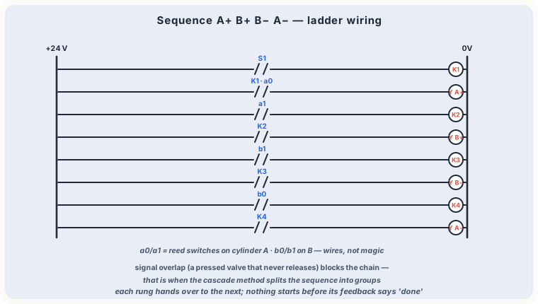
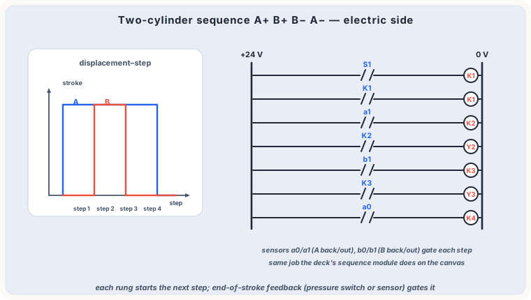
Four rungs, four steps: each relay is guarded by the end-position sensors of the previous step.
Step chain, rung by rung
Exercise classic A+ B+ B− A− (clamp, feed, retract, unclamp): relay K1 runs when START and home signals a0 AND b1 are true; K1's contacts drive coil Y1 (A extends). Sensor a1 fires K2 → B extends; b1 fires K3 → B retracts; b0 fires K4 → A retracts. Every rung is a tiny AND: condition from the sensors, permission from the previous relay.
Signal storage techniques
Relay latching — one pulse stores a state until RESET (previous lesson).
Double-solenoid valve — the valve itself is the memory: a short pulse on "a" sets it, on "b" resets it; no continuous coil current needed.
On-delay timer — "hold 2 s at the end position, then retract" (dwell for quality, glue, welding…).
Counter/preset relay — repeat the cycle N times, then stop and signal.
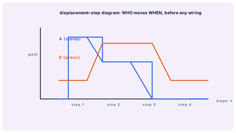
Design rule from the Festo exercises: draw the displacement-step diagram first, then name every sensor, then write the rungs. Never wire "from memory".
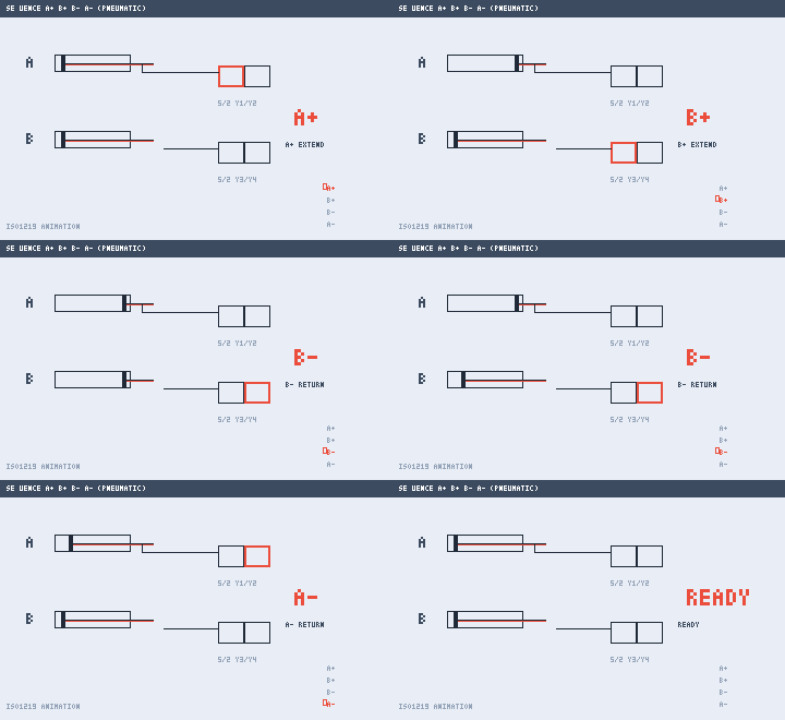
In motion: A+ B+ B− A− — four steps, each guarded by its sensor.
pneumaticsintermediate✓ read
Time-delay, pressure-sequence and quick-exhaust circuits
Three classic pure-pneumatic specials: dwell timers from restrictor + volume + 3/2, pressure-triggered next steps, and the little valve that makes cylinders fast.
≈ 7 min read
Not everything needs a PLC. Three small components deliver timing, pressure logic and speed directly in the air lines.
Time-delay valve
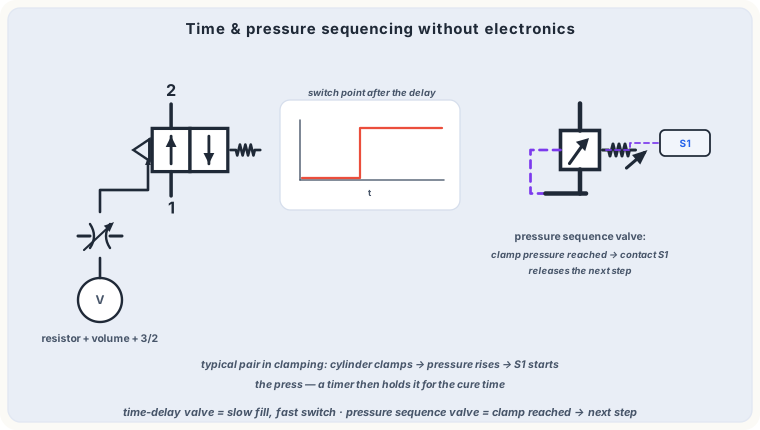
A restrictor + small air volume + 3/2 valve: the signal slowly fills the volume; when threshold pilot pressure is reached, the 3/2 switches. Adjustable 0–30 s. Connect it normal-closed for an on-delay, reversed for off-delay. Typical job: clamp dwell, filtered start signals (ignore bounces), end-position acknowledge.
Time as a signal: fill a volume; pressure as a trigger: switch at the threshold.
Pressure-sequence valve
A 3/2 that switches when line pressure exceeds its setting — the pneumatic pressure switch without electricity. Circuit pattern: "drill down until the counter-pressure from the block signals part-contact, then advance slowly".
Quick-exhaust valve
A tiny disc valve mounted directly on the cylinder port: flow goes in normally through the small throttle, but exhaust dumps to atmosphere at the port instead of traveling back through the metre of tube to the valve. The classic way to retract a cylinder at full speed.
The Pneumatic Studio includes all three — place a time-delay valve in a circuit and watch its pilot pressure climb in slow motion during simulation.
pneumaticsadvanced✓ read
Multi-actuator circuits: signal overlap and the cascade
Why A+ B+ B− A− jams a naive control, how to split a sequence into groups that never collide, and how reversing valves clear blocked pilot signals.
≈ 8 min read
Single-actuator controls are forgiving — every sensor signal has exactly one meaning. With two or more cylinders the same signal can be needed twice, and the classic problem appears: signal overlap.
The overlap problem
Sequence A+ B+ B− A− with limit valves wired straight to the 5/2 pilots: when B leaves b0, its signal arrives at the "extend B" pilot — but B still stands still, so its own limit signal b0 is still pressed and holds the "retract B" pilot. The valve now feels both pilots at once: nothing moves, the machine hangs.
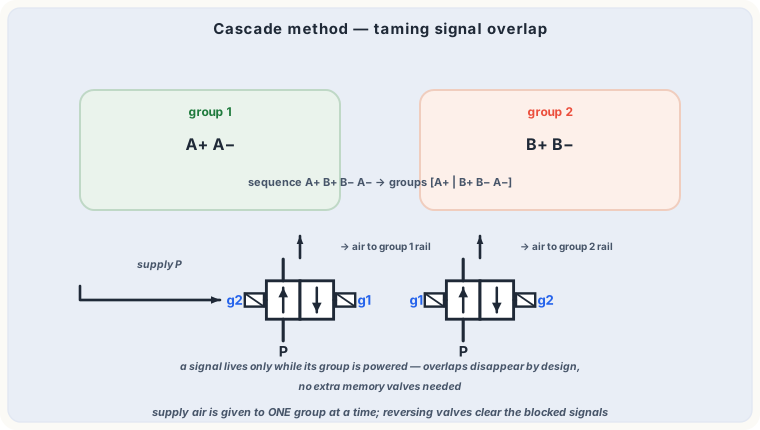
Cascade method: the sequence is split into groups; supply air is switched group by group.
Cascade division
Solution of the Festo course: split the motion chain into groups that contain no cylinder twice. A+ | B+ B− | A− → three groups (or two in smarter splits). A cascade of supply-switching 4/2 valves feeds pilot air to one group at a time — signals of inactive groups are simply dead, so nothing can block.
Reversing valves
The lighter alternative: a roller-lever reversing valve on the offending signal line, flipped by the cylinder itself. It exists exactly to chop the long signal that would otherwise overlap. Co-ordinated motion (feed + clamp + eject) is designed the same way: draw the displacement-step diagram, mark every signal, resolve every overlap on paper.
This is pneumatic programming without a single wire — the same group-splitting logic you later meet in PLC step-chains (SFC/GRAPH).
In motion: the sequence your cascade groups will drive, step by step.
pneumaticsintermediate✓ read
Compressed-air networks: ring mains, drops and drains
How air travels from the compressor room to the machine without losing pressure or carrying condensate — pipe sizing, slope, drop engineering.
≈ 6 min read
The cleanest compressor cannot help a badly piped plant: undersized lines eat pressure (and money), and condensate follows the air straight into the valves.
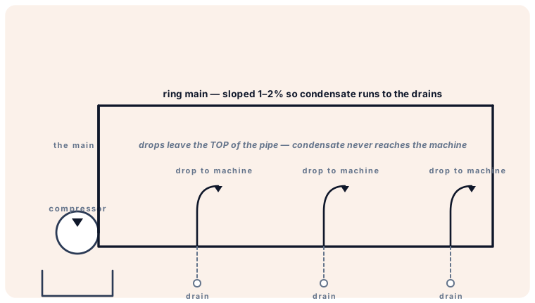
Layout discipline: slope, top drops, bottom drains.
Network layout rules
Ring main around the building — every point is fed from two sides, pressure stays even, sections can be isolated for service.
Slope 1–2 % in the flow direction of the main: condensate runs with the airflow to the low points, never upstream against it.
Drops from the TOP of the main, curving down to the machine — gravity keeps water in the main; at the bottom of each main leg sits an automatic drain.
Machine-side service unit (filter + regulator) per station — as in the FRL lesson.
Sizing
Size by total consumption plus simultaneity and growth. As orientation: 6–10 m/s in mains; every bar of Δp at the tool is ≈ 7 % wasted compressor energy. Materials: galvanised steel, stainless, aluminium profile systems or PE grid lines — modern aluminium nets assemble without threading and never rust.
A plant that "loses pressure at shift start" usually has an undersized ring or a bottleneck fitting — log pressure at the FRL BEFORE blaming the compressor.
hydraulicsintermediate✓ read
Electro-hydraulics I: solenoid valves and logic control
Power section meets signal section: direct and relay-switched solenoid DCVs on single- and double-acting cylinders, with the Boolean view of the classic exercises.
≈ 8 min read
Electro-hydraulics pairs oil's force with electricity's logic. System structure (Festo model): power section (pump, valves, cylinder), signal section (sensors, relays/PLC), and the interface — the solenoid on the valve.
The pressure switch B1 is the ear of the electrical side: it reports the oil side's state.
Basic switching exercises, generalised
Direct control — button drives coil Y1 of a 3/2 (single-acting) or 4/2 (double-acting): press = move, release = return. Simple and perfectly valid for one-shot operations.
Via relay — button drives K1, K1 drives Y1: contacts multiply, voltage drops disappear over distance, and logic can be inserted.
Signal reversal — use the NC contact / spring-centered 4/3: the cylinder is only driven as long as commanded, then positively stops holding mid-travel.
The Boolean view
Contacts in series = AND (guard AND start), in parallel = OR (jog from panel OR remote). NC gives NOT. The XOR circuit (two stations, exactly one active) from the assembly-line exercise is two AND-NOT branches — worth drawing once by hand.
Rule of thumb from the Festo exercises: one relay per state, one solenoid per motion command. Extra cleverness in contacts — never in coils.
hydraulicsadvanced✓ read
Electro-hydraulics II: latching and sequence control
Clamp → press → release without a PLC: signal storage with double-solenoid valves, electrical set/reset, speed stages and pressure- or path-dependent sequences.
≈ 9 min read
Real machines chain motions: clamp the part, feed the tool, retract, unclamp. Two families of memory solve it.
Storage on the fluid side vs the electrical side
Double-solenoid DCV — pulse "a" strokes the spool; it stays (detent/friction) until "b" pushes back. The valve IS the memory — secure against power loss, tolerant to contact bounce.
Relay latching — coils switch cleanly NO/NC; the latched rung drives a single-solenoid spring-return valve. Clearer to extend, watch power-loss reset behaviour.
Five rungs from clamping to release — guarded by the pressure switch and timers.
Sequence by pressure or by position
Clamp → press is typically pressure-dependent: pressure switch B1 closes only when clamp pressure is truly reached (part present, no slip) — then Y2 feeds the press. Retraction is path-dependent: an inductive sensor at the end position starts the return. Add a throttle check for a controlled working feed and an on-delay for dwell at depth; add a counter and an AUTO latch for continuous cycling until N parts are done.
Debugging order on such machines: mechanical pressure first (gauge!), then the fluid state (valve position), only then the ladder page by page.
hydraulicsintermediate✓ read
Hydraulic motors: continuous rotary power
Gear, vane and piston motors, torque from Δp and displacement, speed from flow — and where rotary actuators beat cylinders.
≈ 6 min read
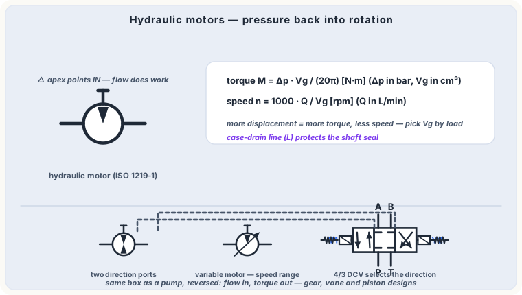
A hydraulic motor is a pump run backwards: pressurised oil in → shaft torque out. Same families, same physics — the displacement Vg is again the master spec:
Circle with inward triangle: energy conversion INTO the system.
Types
Gear motors — simple, robust, cheap; up to ~250 bar, modest startup torque; winches, conveyors, fans.
Vane motors — smooth at low speed, medium pressure.
Axial/radial piston — the heavyweights: high pressure, high start-up torque, precise low-speed control (crawler drives, rotary heads).
Working with motors
Pressure rises only with the load torque — an unloaded motor spins at nearly zero pressure. Leakage oil (case drain — the third small line!) must run directly to tank unpressurised, or the shaft seal dies. For reversing drives use a 4/3 with closed centre plus cross-line reliefs protecting both legs against overrunning-load pressure spikes.
Need rotation within an angle (clamping, tilting)? Use a rotary actuator (vane or rack-pinion "scotch yoke") — the cylinder's rotary sibling.
hydraulicsbeginner✓ read
Gauges, sensors and test points: measuring in hydraulics
Bourdon-tube gauges, electronic pressure and flow sensors, temperature monitoring — the instruments that turn troubleshooting from guessing into reading.
≈ 6 min read
Everything you have calculated in the previous lessons (p, Q, v, force) is only verifiable if you can measure it — that is why professional power units have test points at every critical leg.
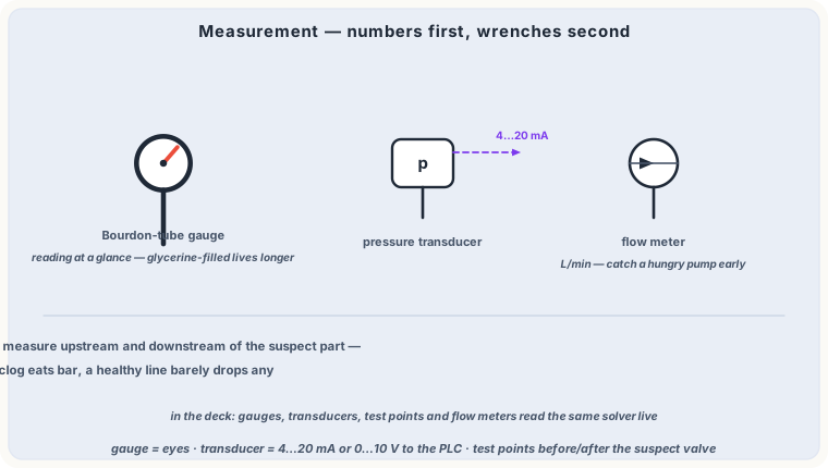
Mechanical or electronic — the question is the same: p, Q, θ?
The toolkit
Bourdon-tube pressure gauge — coiled flat tube straightens with pressure; robust, glycerine-filled for pulsating lines. Choose the scale so working pressure sits at ~75 % of full scale.
Pressure sensor / switch — 4–20 mA or 0–10 V to the PLC; a switch gives a contact at a setpoint (the B1 of the electro-hydraulic lessons).
Flow meter — turbine, gear or oval-wheel; indispensable when comparing pump delivery across operating points.
Temperature — level/temperature switches in the tank guard oil life: sustained >80 °C halves oil and seal service life rapidly.
Test-point discipline
Measure at defined points in a defined operating state, write the values down, compare against commissioning values. A relief drifting 20 bar down or a pump losing 30 % flow is visible months before failure — if you measured.
The studios' gauge and pressure-switch components exist exactly to build this habit: instrument first, conclude second.
hydraulicsadvanced✓ read
Proportional valves: characteristic curves and dynamics
Hysteresis, inversion range, response threshold, pressure curves and step response — reading a proportional valve the way its designer does.
≈ 8 min read
A proportional valve is fully described by its characteristic curves. Learn to read them and selection + commissioning become engineering instead of mystery.
Pressure valves: output pressure vs command — nearly linear; the slope is the gain (bar per % / per mA).
Flow/directional valves: flow vs command at constant Δp — starts at the deadband (positive overlap, often 10–30 % of command; crossed with feedback spools to near zero).
Hysteresis — friction + magnetic remanence: the up-branch differs from the down-branch by a few %; better valves ≤ 1–3 %.
Response threshold / inversion range — the smallest command change the valve answers to (≈ 0.1–1 %); the floor of your positioning accuracy.
Dynamics
Step-response time to 90 % and the −3 dB (or −90°) frequency tell how fast the valve follows: typical direct-acting 20–80 ms, piloted faster stages exist for demanding axes. Bode plots in datasheets pair amplitude and phase — for loop tuning, phase margin is the interesting one.
Application limits
Max flow grows with √Δp over the metering edge — doubling rated Δp gives only ~40 % more authority. Overspeed conditions and pressure shocks need their own protections (counterbalance, reliefs) — proportional spools are metering edges, not safety valves.
In the Hydraulic Studio, the proportional valve and amplifier components expose gain, ramp and deadband directly — watch the step response change as you edit them.
hydraulicsadvanced✓ read
Proportional control in practice: open and closed loops
From the manually switched feed drive to closed-loop positioning: the signal chain, speed profiles, and when closed loop is worth its sensor.
≈ 9 min read
The Festo training path builds the same feed drive three times: manual hand lever → switching solenoid valves with limit switches → proportional. The proportional version wins on smoothness, programmability and reproducible speed profiles.
The signal chain
Setpoint (potentiometer, PLC analog output) → amplifier (ramps, gains, dither) → proportional valve → cylinder/motor speed. Open loop: the machine trusts the chain. Closed loop: a position or speed sensor reports the truth back to a controller that compares, computes error Δe and corrects the command continuously.
The loop: only the measured truth decides the final motion.
Open loop vs closed loop
Open — cheaper, stable by nature; accuracy limited by oil temperature, load and valve hysteresis (think ±1–3 % of stroke).
Closed — position accuracy into the 0.1–0.5 % range with repeatability independent of load; needs sensor, controller, tuned gains, and respects the axis's natural frequency (valve must be ~4× faster).
Practical patterns
Speed profiles with ramps avoid jerking loads and compressive shocks; a slowdown point before every end position (taught via PLC cams) gives soft, fast cycles. Watch energy: proportional metering throttles → heat; over-centre loads need counterbalance valves; minimal leakage circuits protect warm-up accuracy. Modern axes move the whole loop INTO the valve (on-board electronics, digital fields).
Studio exercise: build a feed axis with the proportional valve, set a pure P-gain amplifier, then observe overshoot as you raise gain — the exact trade-off of a real loop.
generalintermediate✓ read
Function diagrams and control documentation
Displacement-step diagrams, function charts, circuit and terminal diagrams — the paper trail that makes machines designable, testable and repairable.
≈ 7 min read
A machine that exists only in someone's head is unrepairable. The Festo documentation set has four views — each answers a different question.
1. Displacement–step diagram (function diagram)
One line per actuator, steps on the x-axis, path/stroke on the y-axis: WHO moves WHEN. Drawn before any component is chosen — it is the contract of the control design, and reveals signal overlap at a glance.
Clamp (A) must arrive and hold before press (B) runs — the diagram says it without a word of code.
2. Function chart
The ladder-friendly tabulation: steps down, actuators and sensors across, X marks active elements per step; the direct bridge into relay/PLC programming (SFC-style).
3. Circuit diagrams
The ISO symbol schematic (fluid) and the electrical ladder diagram (control). Elements numbered by circuit groups: 0 = supply, 1 = first drive, 2 = second…; every element's mark in the drawing = its mark in the machine.
4. Terminal and wire diagrams
For the cabinet builder: every wire numbered, every terminal labelled; the solenoid in rung 3, wire 14, terminal X2:7 — one identity from drawing to screwdriver.
Adopt the discipline on small jobs: sketch the displacement-step diagram on paper before opening a studio app — the circuit almost designs itself afterwards.
generalbeginner✓ read
Safety first: stored energy, jets and electricity
The non-negotiable rules of fluid-power and electrical maintenance: depressurise, lock out, verify — and respect the pinhole jet.
≈ 6 min read
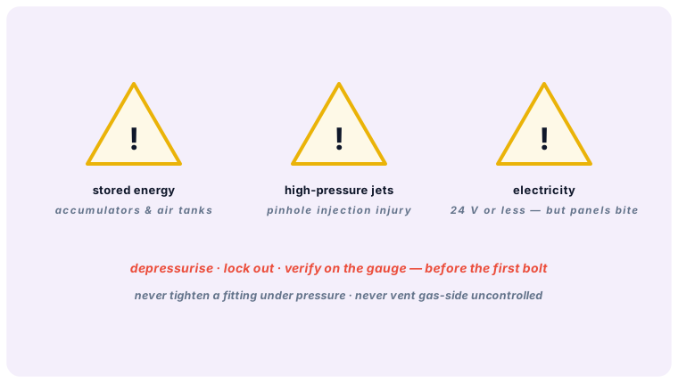
The three hazard families of fluid-power work.
Stored energy stays on duty
Switched off ≠ de-energised. Accumulators hold hundreds of bar for hours; compressed-air receivers too; suspended cylinder loads can descend on their own. The ritual before any intervention: Lock out the start → release pressure at the designed bleed point → verify zero on the gauge → only then work (LOTO — lock-out, tag-out).
The invisible cutter
A pinhole-leak jet at 200 bar penetrates skin without pain at first and injects oil under it — a surgical emergency, not a band-aid case. Never trace a leak with the hand; use cardboard, gauge checks, or the shut-down method.
Electricity: respect, not fear
Control circuits at 24 V DC are body-safe; their knowledge risk remains (a 24 V mistake still drops a press). Machine mains, transformers and large capacitor banks belong to qualified hands. Effects of current on the body are current-path and time dependent — the professional rule-set (isolation, covers, RCDs, color-of-cables discipline) exists in every plant for a reason.
House rules that prevent 90 % of incidents
Never tighten or loosen a fitting under pressure; never vent the gas side of an accumulator uncontrolled — connect the charging rig.
Nitrogen ONLY for accumulator pre-charge — oxygen/oil-air compressed mixtures are explosive.
After work: function-test against the checklist, at low pressure first, guards back on.
Make it culture: the slowest safe repair beats the fastest unsafe one — every time, without exception.
hydraulicsintermediate✓ read
Designer track H1 — Spec the job: from load to bore and system pressure
Step 1 of every hydraulic design: list the load, choose the working pressure, and calculate the cylinder bore with reserve. Worked numbers included.
≈ 9 min read
This is the first lesson of the Hydraulic Designer Track. Each track lesson follows the same pattern: design decision → formula → worked numbers → build it in the Studio. Follow them in order and you will have dimensioned a complete, realistic machine by the end.
The machine brief (our running project)
We will design a hydraulic press/lift: it must raise a 3 200 kg load (~31.4 kN) by 400 mm in about 4 s, then hold and lower it controlled. Keep this brief — the next lessons reuse it.
Step 1 — Choose the working pressure
Pressure is a design choice, not a given: higher pressure → smaller, cheaper components, but more noise, leakage stress and filtration demands. Industrial standard bands:
Light duty / lifts: 63 – 100 bar
General machine tools: 140 – 210 bar
Presses / mobile: 250 – 350 bar
For our lift we pick p = 160 bar — a good middle band with standard NG6 components.
Step 2 — Bore from the force equation
A ≥ F / (p · ηhm) = 31 400 N / (16 MPa · 0.9) ≈ 21.8 cm² d = √(4A/π) ≈ 52.7 mm → choose ISO bore Ø 55…63 mm (we take Ø 63 mm, A = 31.2 cm²)
Never round down. The standard series is 25, 32, 40, 50, 63, 80, 100, 125, 160 mm. With Ø 63 the static pressure at the load is only pstatic = 31 400 / 31.2 cm² ≈ 101 bar — comfortable reserve under our 160 bar network.
Step 3 — Rod diameter & buckling pre-check
Standard rods are ~0.5–0.7 × bore: choose rod Ø 36 mm → annulus area AR = 31.2 − 10.2 = 21.0 cm², area ratio φ ≈ 1.49. With a 400 mm push stroke the rod is not slender (check the manufacturer's buckling table — 36 mm rod at 400 mm free stroke is rated far above 31 kN). Details: lesson “Selecting a hydraulic cylinder”.
🏗 Studio exercise H1
Open the Hydraulic Studio and place: power pack (set relief 160 bar, pump ~12 l/min), a 4/3 directional valve, and a double-acting cylinder Ø 63/36 × 400 mm with a 3200 kg load.
Simulate and hold the valve at extend: watch the gauge climb to ≈ 101 bar before the cylinder moves — exactly your hand calculation.
Reduce the bore to Ø 50 mm and repeat: the required pressure rises above 160 bar and the relief cracks — you have just seen why step 2 matters.
Deliverable of this lesson: a one-line spec — “Ø 63/36 × 400 mm at 160 bar” — that every following lesson builds on.
hydraulicsintermediate✓ read
Designer track H2 — Flow, speed and line sizing
Turn the motion requirement into a pump flow, then size suction, pressure and return lines so velocity and pressure drop stay in the green bands.
≈ 9 min read
Design decision #2: how much oil must move, and through which pipes? Continuing our project: Ø 63/36 × 400 mm, lift in ≈ 4 s.
Step 1 — Speed from the process, flow from the speed
v = stroke / t = 400 mm / 4 s = 100 mm/s (extend) Q = v · A = 0.1 m/s · 31.2 cm² = 18.7 l/min → pump 20 l/min
Retract comes free: the same 20 l/min on the annulus (21 cm²) gives v ≈ 0.16 m/s — the classic faster return. If the cycle time is unacceptable you either raise Q or accept it; that decision belongs here, not later.
Step 2 — Velocity classes (the table every designer memorises)
Suction: 0.5 – 1.5 m/s (cavitation-safe)
Return: 2 – 4 m/s
Pressure: 3 – 6 m/s up to ~150 bar, 5 – 7 m/s above
Step 3 — Inner diameter from velocity
d (mm) = √( 21.2 · Q (l/min) / v (m/s) ) Pressure line @ 5 m/s: d = √(21.2·20/5) ≈ 9.2 mm → DN 10 hose Suction @ 1 m/s: d ≈ √(21.2·20/1) ≈ 20.6 mm → DN 20/25 Return @ 3 m/s: d ≈ √(21.2·20/3) ≈ 11.9 mm → DN 12
Step 4 — Verify pressure drop, don't guess it
Every metre of line and every fitting eats pressure (Δp ∝ v²). On a 20 l/min system a badly chosen DN 6 pressure line can burn 15–25 bar as pure heat. Rule: total pressure-line losses ≤ 5–10 % of working pressure at full flow. The Studio colours undersized lines red in the pipe-sizing report — treat that report as your design checker, not decoration.
🏗 Studio exercise H2
In your H1 circuit set the pump to 20 l/min and measure extend speed: ≈ 107 mm/s (simulation includes valve losses — slightly above your 100 mm/s target ✓).
Open the pipe sizing tool: set every pressure line to DN 10, suction to DN 25, return to DN 12, and read the velocities against the table above.
Now force DN 6 everywhere and re-simulate: watch pump pressure climb and oil temperature rise — that is a real machine destroying itself slowly.
Designer habit: write Q = 20 l/min and the three diameters onto the schematic. Real drawings always carry the design flow next to the pump symbol.
hydraulicsintermediate✓ read
Designer track H3 — Choose the directional valve: positions, blocks and actuation
The 4/3 valve is a design statement: what may the machine do when stopped, starting, and mid-stroke? Select left, center AND right blocks like a professional.
≈ 8 min read
Most beginners pick a “4/3 valve” and stop thinking. A designer picks three blocks — left, center, right — because each switching position is a machine state with consequences.
Step 1 — Count positions and ports from the sequence
Our press must: extend (work) → stop+hold → retract. Three states = 3 positions. Double-acting cylinder = 4 ports. → 4/3 valve. (2-position valves suit bang-bang motions without intermediate stop.)
Step 2 — What happens at rest? → the CENTER block
Closed center — all ports blocked: the load is hydraulically locked (our choice — a 3.2 t load must not sink), but the pump unloads over the relief at full pressure = heat. Fine for short cycles.
Tandem center — P→T open, A/B blocked: load locked AND pump idled at ~5 bar. The energy-conscious standard for load-holding.
Float center — A/B→T: the cylinder can be pushed by hand (machine set-up mode).
Open center — everything to tank: only for systems that may never hold a stopped load.
Step 3 — The WORKING blocks (left and right) are selectable too
In the Studio's valve inspector you can now choose the left and right envelopes independently:
Parallel (P→A, B→T / P→B, A→T) — the normal drive blocks.
Closed / capped block — a 3-position valve that only works in one direction plus neutral (e.g. lift-cylinder that only powers up, gravity loads down through a flow control).
Regenerative block — P→A and B→A: rod-side oil joins the pump flow into the cap end = rapid approach, then you switch to a normal block for the press stroke. Classic fast-approach/work-stroke press design.
Step 4 — Actuation
Solenoid (electrohydraulic sequences, our project), manual lever (jog/maintenance), pilot pressure (large values or logic). Rule: choose the spring arrangement first — spring-centered with 2 solenoids for 3 positions, spring-offset with 1 solenoid for 2 positions.
🏗 Studio exercise H3
Select your 4/3 valve and set: center = tandem, left = parallel, right = crossover.
Simulate center: pump pressure collapses to a few bar (tandem unload) while the loaded cylinder stays put — check both in the gauges.
Actuate left then right and note the cylinder direction flip between parallel and crossover blocks — no rewiring needed.
Try right = regenerative: measure extend speed jump. Now you understand the “REGEN FAST APPROACH” example circuit.
Interview test for any valve choice: “At every position, where does the pump oil go, and what holds the load?” If both have crisp answers, your blocks are right.
hydraulicsadvanced✓ read
Designer track H4 — Speed control: meter-in vs meter-out, set with a method
Decide where the throttle lives, then commission it with a repeatable 4-step procedure instead of turning screws until it “looks right”.
≈ 8 min read
Our 3.2 t load must not free-fall during lowering. That single sentence decides the speed-control topology — the throttle goes on the rod side (meter-out for the retract/lower motion).
Step 1 — Load analysis (the deciding question)
Resistive load (pushes back, e.g. pressing, feeding a tool): meter-in or meter-out both work; meter-in is simpler.
Overrunning load (pulls the cylinder, e.g. lowering a weight, decelerating a flywheel): meter-out is mandatory — otherwise the cylinder runs away and cavitates on the supply side.
Load changes sign: meter-out, and consider a counterbalance valve for big vertical masses.
Step 2 — Understand the meter-out pressure intensification
Throttling the rod side of our φ≈1.5 cylinder means the trapped rod-side pressure can reach prod ≈ pcap·φ + F/AR. Check hose and seal ratings on the return side — a “return line” in a meter-out lowering circuit is a pressure line!
Step 3 — The commissioning procedure (write it into your documentation)
Open the flow-control fully, run the axis, record max speed.
Close the throttle until speed ≈ 1.1× target with the heaviest expected load.
Run 5 cycles, watch stability; then re-check with the lightest load (a plain throttle is load-dependent — if the speed spread is unacceptable, upgrade to a 2-way pressure-compensated flow control).
Mark the setting (paint dot / lock nut / turns-from-closed in the service manual).
🏗 Studio exercise H4
Place a flow control with bypass on the rod side between valve B port and cylinder (orient the check valve for free extend, throttled retract).
With the load attached, extend (free flow), then retract with the screw at 100 %, 50 %, 20 %: log the three lowering speeds into a small table — your calibration curve.
Remove the load and repeat: observe the load-dependence. Now swap in a pressure-compensated flow control and notice the spread shrink. You have just made the design decision of every professional circuit.
Real plants lose hours to “mystery speed changes”. 90 % of them are an untracked throttle screw. Calibrate, record, lock.
hydraulicsadvanced✓ read
Designer track H5 — Pressure protection, clamping and emergency reserves
Set the relief with the 1.15× rule, decide when a reducing valve is required, and add an accumulator for hold-at-pressure and power-failure cases.
≈ 9 min read
Design decision #5: protecting the system at its edges — overpressure, branch pressure, holding force after the pump stops.
Step 1 — Relief valve setting
prelief ≈ 1.1 – 1.2 × pmax working → our project: 160 · 1.15 ≈ 185 bar… but the pack is sized 160 bar max, so prelief = 160 bar and working p ≤ 140 bar.
Decide the ceiling first, then live 15 % below it. Every component downstream (hoses, seals, gauges) is selected against the relief setting, not against “typical” pressure.
Step 2 — Branches at reduced pressure
If our machine also clamps a delicate part (needs only 60 bar of clamp force), a pressure reducing valve in the clamp branch beats a separate power pack by a mile. It is normally open and throttles when downstream pressure exceeds the setpoint — different animal from the relief (normally closed). The Studio examples “Reduced-pressure clamp branch” and “PRESSURE CLAMP” demonstrate both.
Step 3 — Must the load hold pressure without the pump? → accumulator
Press-hold, emergency descent, pump-failure completion of a safety motion: all need stored energy. Quick sizing for our hold case:
Example: leak compensation for 60 s at ~5 ml/min → Vusable ≥ 0.3 l; with p₀=65 bar, p₁=100, p₂=160 bar → V₀ ≈ 0.75 l → choose a 1 l bladder accumulator. Always with: safety block (relief + drain), nitrogen charging rig, and the isolation valve before any service.
Step 4 — Failure-mode table (fill one for every real design)
Pump stops mid-lift → load held by closed/tandem center + accumulator reserve ✓
Hose bursts on rod side → counterbalance/check-valve strategy (track H4 decision pays off)
Power returns unexpectedly → control must not self-start (e-stop logic, next track lesson)
🏗 Studio exercise H5
Build the ACCUMULATOR CLAMP example and watch the sequence: pump charges, valve centers, the accumulator holds clamp pressure while the pump unloads.
In your own circuit add an accumulator with isolation + drain valve, charge to 160 bar, then stop the power pack: read the clamp pressure decay time.
Set the relief 20 bar below your chosen ceiling and try to reach 160 bar through the cylinder: you can't — and that is exactly the protection working.
Never put an accumulator on a schematic without its drain-and-isolate hardware. In audits this is the first thing inspectors look for.
hydraulicsadvanced✓ read
Designer track H6 — Verify the design: power, heat and the bill of materials
The last 20 % of design work that prevents 80 % of commissioning pain: power balance, heat balance, instrumentation points and a clean BOM.
≈ 9 min read
Your schematic works in simulation. Is it a good machine? Designers answer three numbers and one document before releasing anything.
Check 1 — Hydraulic power and motor size
Phyd = p·Q/600 = 140 bar · 20 l/min / 600 ≈ 4.7 kW with ηpump ≈ 0.85 → motor 5.5 kW (next standard size up)
Check 2 — Heat balance (the silent killer)
All throttled energy becomes heat. Worst case for our press: dwell phases with pump over relief = full 4.7 kW into the oil. Natural tank dissipation ≈ 0.5–1 kW per 100 l. With an 80 l tank we need a return-line cooler ≈ 4 kW, or better: tandem center + load-sensing so the pump idles during dwell. Simulation truth: run your circuit 5 minutes of dwell and watch the oil-temperature metric — over 60 °C sustained means redesign, not a bigger cooler.
Check 3 — Instrumentation points
Minimum professional set: gauge isolator point after pump (M), at valve P, at both cylinder ports, temperature + level switch in the tank, pressure switch where control cares about pressure (our clamp). Every point costs €5 and saves a service hour later. Masses of red gauges in the examples are a habit, not a style.
Check 4 — The BOM (bill of materials)
From your final Studio schematic, write every element with: quantity, type, key spec (Ø 63/36×400, 20 l/min @ 1450 rpm, NG6 4/3 tandem 24 V DC…), and settings (relief 160 bar, throttle position from H4, accumulator pre-charge from H5). Add hose diameters from H2. This document IS the machine for purchasing and service.
🏗 Studio exercise H6 — the capstone
Assemble the complete press: power pack (20 l/min, relief 160), 4/3 tandem-center with solenoids, meter-out flow control on the rod side, Ø 63/36 × 400 cylinder with 3200 kg, pressure switch as clamp-confirmation, gauges at the four points.
Run the full cycle: extend → clamp-confirm (PS1 switches) → center+hold → retract. Record: max pump pressure, both speeds, oil temperature after 3 cycles.
Write the BOM of your circuit and compare each line with the settings you actually simulated. Differences = design bugs found before steel.
Save the circuit to your profile (My Account) — it is the reference solution for the pneumatic track comparison in lesson P2.
If your simulated pressures and speeds match your hand calculations within ~10 %, you are doing professional verification. If not, find the discrepancy — it is always either the model input or the arithmetic, and both are worth catching.
pneumaticsintermediate✓ read
Designer track P1 — Pneumatic axis: sizing, flow and speed at 6 bar
The pneumatic counterpart of H1/H2: bore from force with the 1.3 rule, air consumption for the FRL and compressor check, and exhaust throttling done right.
≈ 8 min read
Pneumatic Designer Track. Project: a pick-and-place pusher must shove a 25 kg box 200 mm in 0.8 s, 30 cycles/min. Friction and return spring eat margin — design margin in pneumatics is not optional.
Step 1 — Bore with the load-factor rule
F = 25 kg · ~0.3 friction µ · g ≈ 74 N… tiny. The speed is the real driver — but start with force anyway:
Fcyl ≥ Fload / 0.7 (η+reserve) ≈ 106 N A ≥ F/p = 106 / 0.6 MPa = 1.77 cm² → d ≥ 15 mm → ISO bore Ø 25 mm
Choose one or two sizes above the arithmetic when in doubt — air is cheap compared to a stalled cycle.
Step 2 — Check mains capacity: air consumption
VNL/cycle ≈ A·s·(p+1) both sides ≈ (4.9+4.1) cm² · 2 dm · 7 ≈ 1.3 NL × 30/min ≈ 39 NL/min — trivial for any shop supply ✓
Step 3 — Speed by conductance, not hope
v ≈ 250 mm/s required. That is fast for pneumatics: size the valve ≥ the cylinder's demand (nominal flow at 6 bar in the datasheet; for Ø 25 at 6 bar & 250 mm/s ≈ 150–250 NL/min — a standard 5/2 with G⅛" ports suffices). Tubing: 6×4 mm for cylinders ≤ Ø 32, 8×6 mm up to Ø 63 — keep runs under ~2 m or speed decays measurably.
Step 4 — Meter-out, always (and why)
Exhaust-air flow controls on both ports. Meter-in on compressible air gives stick-slip: pressure builds behind the piston until static friction breaks, then it jumps. The Studio demonstrates this: set a supply-side throttle and watch the piston stutter; move it to the exhaust side and the motion smooths.
🏗 Studio exercise P1
Build in the Pneumatic Studio: service unit (6 bar) → 5/2 solenoid valve → two exhaust flow controls → Ø 25 × 200 mm cylinder, load 25 kg.
Set both throttles for v ≈ 250 mm/s and verify: full cycle in ≈ 1.6 s including return.
Measure and note the supply pressure dip during the stroke — that dip is your valve+tube conductance report. Increase one throttle to 100 % and watch asymmetry appear.
Spec line for this lesson: “Ø 25 × 200 at 6 bar, 5/2 G⅛, Ø 6 tube ≤ 2 m, exhaust throttles”. Compressed, and it contains everything.
The method that scales from two cylinders to twenty: displacement-step diagram → sensor placement → PLC rungs — built and simulated end-to-end in the Studio.
≈ 10 min read
Design decision of every automation machine: the sequence. Amateurs wire by intuition and debug for days; professionals draw the step diagram first and the circuit almost falls out of it.
Step 1 — Displacement-step diagram (always first)
Machine: feeder pushes a part under a press, press stamps, both retract. Write the motion chain: A+ B+ B− A− (A = feeder, B = press). Draw two lines (A and B) over 4 steps — who moves when. This 2-minute drawing is the contract everything else must satisfy.
Step 2 — Sensors at the decision points
Each transition needs proof the previous motion finished: reed switches a0 a1 b0 b1 at the four end positions. Rule: one sensor per state change you depend on — never infer B extended from “enough time passed” if quality or safety depends on it (use time only for dwell, and a pressure switch when force matters).
Step 3 — The signal-overlap check
Trace every pilot signal's lifetime in the diagram: does any sensor keep its signal into a step where it would command the opposite? In A+ B+ B− A− with bistable valves, b0 lingers — classic overlap. Solutions: cascade air supply by groups, electrical edge evaluation, or — the modern choice — a PLC evaluating conditions each scan.
Step 4 — PLC rungs from the diagram (mechanical translation)
Give each step a memory bit (Studio PLC syntax — one condition, one action per rung):
S1 = START AND a0 AND b0 — step 1 enable: home positions proven.
S1 -> V1 left — A extends (valve V1 to extend).
S2 = a1 → S2 -> V2 left — when feeder arrives, press extends.
S3 = b1 → S3 -> V2 right — press bottom sensor retracts the press.
S4 = b0 → S4 -> V1 right — press home → feeder back; cycle re-arms at a0.
No trapped signals, no air-group plumbing — sensors are PLC inputs, solenoids are outputs, and deleting PLC1 really stops the machine (test it!). That is exactly how a real machine dies when its controller is pulled.
🏗 Studio exercise P2
Open the pneumatic example “Electropneumatic sequence” and study how its rungs map to a step diagram — sketch it on paper.
Delete PLC1 (temporarily!): the sequence must now stop after the first motion. Undo the delete — you have proven the control chain end-to-end.
Wire the 4 rungs above with your own two cylinders, four reed sensors and two solenoid valves. Debug by watching which sensor fires in the log — the same skill as reading a real PLC's input LEDs.
Add a dwell: press holds 2 s at b1 via a timer relay (b1 -> T1 start … T1 -> V2 right).
This method — diagram, sensors, overlap check, rungs — is exactly the Festo designer workflow. Machines designed this way commission in hours, not weeks.
hydraulicsbeginner✓ read
Hydraulic power pack (HPU)
The heart of every system: tank, motor, pump and relief valve in one unit.
≈ 5 min read
The heart of every system: tank, motor, pump and relief valve in one unit.
Hydraulic power pack (HPU)
What it is
The power pack converts electrical energy into hydraulic flow. In the Studio it is one symbol exposing P (pressure) and T (tank) ports, but physically it contains the tank, the electric motor, the pump, the pressure relief valve and usually the breather, level gauge and suction strainer.
How it works
The motor drives the pump at constant speed (4-pole ≈ 1450 rpm at 50 Hz). The pump draws oil from the tank through the suction line and delivers a fixed flow to P. When the actuators stop consuming flow, pressure climbs until the relief valve opens and dumps oil back to T — limiting the maximum system pressure.
Specify by pump flow (l/min), relief setting (bar, the system ceiling!) and motor power (kW). Tank volume is typically 2–4× the pump flow per minute for stationary units. Relief = 1.1–1.15× the highest working pressure.
Typical applications in circuits
Every stationary hydraulic machine: presses, lifts, clamps, test rigs.
Compact "mini power packs" for docks, tail lifts and tools.
In simulation: the single energy source of every circuit — gauges, temperature and efficiency metrics all trace back to it.
Studio exercise: Build a minimal circuit (power pack → 4/2 valve → cylinder), note pump pressure at idle vs under load, then set the relief 20 bar lower and watch the cylinder stall exactly at the new ceiling.
hydraulicsbeginner✓ read
External gear pump
The workhorse: simple, cheap, robust fixed-displacement delivery.
≈ 5 min read
The workhorse: simple, cheap, robust fixed-displacement delivery.
External gear pumpThe pump keeps the loop alive — flow never stops, valves only steer it.
What it is
Two meshing gears in a tight housing transport oil in the tooth gaps from suction to pressure side. It is the most common industrial pump because of its tolerance to dirt, low price and simple construction.
How it works
As the gears unmesh on the suction side, the expanding volume draws oil in; the oil travels around the housing wall (never between the teeth!) and is squeezed out where the gears mesh again. Flow per revolution is fixed by the tooth volume (displacement Vg).
Q (l/min) = Vg (cm³/rev) × n (rpm) × ηvol / 1000
Key parameters & selection
Sizes 0.25–250 cm³/rev, continuous pressures to ~250 bar (300 peak). Volumetric efficiency 85–95 %, drops with wear and with low-viscosity hot oil. Noisy above ~2000 rpm.
Typical applications in circuits
Standard choice for cost-sensitive power packs up to medium pressure.
Multiple-section gear pumps feed independent circuits from one shaft.
As lubrication/scavenge pumps inside transmissions.
Studio exercise: In the Studio power pack, compare relief heating at full flow: simulate a blocked circuit 60 s and watch oil temperature climb — that is a gear pump working purely against the relief.
hydraulicsintermediate✓ read
Variable-displacement piston pump
Swashplate control: flow follows demand instead of the relief valve.
≈ 6 min read
Swashplate control: flow follows demand instead of the relief valve.
Variable-displacement piston pumpThe pump keeps the loop alive — flow never stops, valves only steer it.
What it is
An axial-piston pump whose displacement is adjustable while running — usually by tilting the swashplate. A compensator piston moves the plate against a spring, so the pump itself regulates its output.
How it works
When system pressure reaches the compensator setting, a small control spool admits pressure to the destroking piston: the swashplate flattens and the pump delivers only leakage/compensation flow. Pressure stays constant while flow follows the consumers — no relief throttling, far less heat.
Qmax = Vg,max × n / 1000 | standby loss ≈ 2–5 % of rated power
Key parameters & selection
Pressures to 350 bar continuous. Controls: pressure compensator, load-sensing, power limiting, electric proportional. More expensive and more sensitive to contamination (ISO 4406 class ~19/17/14 or better) than gear pumps.
Typical applications in circuits
Machines with long dwell phases (injection molding, presses) where a fixed pump would overheat the oil.
Load-sensing mobile systems: flow on demand saves fuel.
Servo-hydraulic test rigs needing fast pressure/stroke control.
Studio exercise: Compare idle behavior: simulate 30 s of dwell with a fixed pump (relief flow = full heat), then imagine the variable pump at standby — that contrast is why big machines are pressure-compensated.
hydraulicsbeginner✓ read
Hand and emergency pumps
Muscle-powered pressure: for service, rescue and remote tools.
≈ 4 min read
Muscle-powered pressure: for service, rescue and remote tools.
Hand and emergency pumpsThe pump keeps the loop alive — flow never stops, valves only steer it.
What it is
A lever-driven piston pump, often two-stage (large piston for fast prefill, small piston for high pressure). No electricity needed — the standard backup when the power pack fails or is unavailable.
How it works
The lever strokes a small piston; check valves rectify the motion so each stroke pushes a small volume toward the consumer. Two-stage designs switch automatically at a set pressure: high flow below ~20 bar, then a small plunger continues up to 700+ bar.
Key parameters & selection
Typical: 1–20 cm³ per stroke, 160–700 bar. Oil reservoir integrated. Handle effort ≤ 350 N at full pressure.
Typical applications in circuits
Emergency operation: retract a cylinder or release a clamp during power failure.
Pre-charging and testing small circuits on the bench.
Studio exercise: Think through your own circuit: if the power pack dies mid-lift, where would a hand pump need to connect? That is exactly the "emergency release" study in the Studio examples.
hydraulicsbeginner✓ read
Hydraulic motor (gear type)
A pump in reverse: pressurized oil in, shaft torque out.
≈ 5 min read
A pump in reverse: pressurized oil in, shaft torque out.
Hydraulic motor (gear type)
What it is
The gear motor converts flow back into rotation. Externally identical to a gear pump, internally modified (balanced bearings, case drain) because it starts under load and may rotate both directions.
How it works
Pressure acts on the tooth surfaces: the imbalance between the pressure and suction sides creates torque. Flow rate sets the speed; the pressure difference sets the torque. The third small port (case drain) returns internal leakage to tank without pressure.
To 250 bar, 500–4000 rpm, modest starting torque (85–90 % of theoretical). Always connect the case drain directly to tank — back pressure kills the shaft seal within hours.
Typical applications in circuits
Conveyor and mixer drives, fan drives, winches.
Rotary fixtures where an electric motor is impractical (ATEX zones).
Series connection for synchronized multi-motor drives.
Studio exercise: Simulate a motor on a throttle-controlled supply: watch rpm follow flow linearly while pressure follows only the load torque — the two equations above, live.
hydraulicsintermediate✓ read
Piston motors (axial & radial)
The heavyweights: high pressure, high starting torque, precise low speed.
≈ 5 min read
The heavyweights: high pressure, high starting torque, precise low speed.
Piston motors (axial & radial)
What it is
Axial-piston motors (bent-axis or swashplate) and radial-piston motors deliver the highest torque densities. Radial designs (multi-lobe cam) rule LSHT duty: huge torque at a few rpm.
How it works
Pressure on the pistons creates force components against the swashplate or cam ring; the geometry converts them to shaft torque. Variable versions change displacement on demand — high displacement for starting, low for speed.
Key parameters & selection
To 450 bar; starting torque up to 95 %; radial LSHT units to several 10 000 Nm. Require clean oil (servo-grade filtration for high-speed axial types).
Typical applications in circuits
Winches and slew drives in cranes and excavators.
Crawler/propel drives with two-speed or stepless variable motors.
Mixers, crushers: steady torque at very low rpm.
Studio exercise: Compare gear vs piston motor in the Studio: same Δp and displacement — the piston unit holds torque at near-zero speed where the gear motor stalls (internal leakage).
hydraulicsbeginner✓ read
Double-acting hydraulic cylinder
The universal linear actuator: force in both directions, asymmetric speeds.
≈ 6 min read
The universal linear actuator: force in both directions, asymmetric speeds.
Double-acting hydraulic cylinderOne full duty cycle of a 4/3-driven cylinder: extend, centre lock, retract.
What it is
A piston on a rod inside a tube, with a port on each chamber. Cap (piston) side area AK is larger than the annulus AR on the rod side — the source of unequal forces and speeds.
How it works
Pressure on the cap side extends the rod; pressure on the annulus retracts it. Same flow → faster retraction (smaller area). Same pressure → larger extend force (larger area). The ratio φ = AK/AR (1.25–2) must enter every sizing calculation.
Fout = p · AK | Fin = p · AR | v = Q / A | φ = AK/AR
Key parameters & selection
Bores 25–400 mm, rods 0.4–0.7× bore, strokes to 3+ m. Add end cushioning for kinetic energy above ~0.1 m/s with heavy loads; consider buckling for long push strokes (Studio inspector computes both).
Typical applications in circuits
Literally every linear task: presses, lifts, clamps, steering, tilting.
Regenerative circuits exploit the area difference for fast approach + work stroke.
Meter-out speed control protects against overrunning loads on vertical axes.
Studio exercise: In the Studio: feed 20 l/min to a Ø 63/36 cylinder, read 107 mm/s extend and ~159 mm/s retract — verify both numbers by hand (v = Q/A).
hydraulicsbeginner✓ read
Single-acting cylinder & plunger ram
One port, one direction: returned by spring, load or gravity.
≈ 4 min read
One port, one direction: returned by spring, load or gravity.
Single-acting cylinder & plunger ramOne full duty cycle of a 4/3-driven cylinder: extend, centre lock, retract.
What it is
Only the cap chamber is pressurized; the rod side is vented. Retraction comes from a return spring, the load itself (press rams, car lifts) or external force. Plunger rams have no piston at all — the rod IS the pressure surface.
How it works
Oil in → extend (minus spring force in spring-return types). The 3/2 valve releases the chamber to tank → the spring or gravity pushes oil back. Simple, cheap, and needs no valve outlet management on the retract side.
Key parameters & selection
Force = p·A minus spring/gravity. Spring-return strokes limited to ~100 mm (spring packaging); plunger rams to 1 m+. Always provide a breather on the vented side — a plugged breather stalls the return.
Typical applications in circuits
Workshop presses and simple lifts (load-return).
Clamps and ejectors (spring-return).
Car hoists: one big plunger, descend on a flow control.
Studio exercise: Build a single-acting lift in the Studio with a 3/2 valve: extend full speed, then lower through a meter-out flow control and measure the difference.
hydraulicsintermediate✓ read
Telescopic cylinder
Long stroke from a short body: staged sleeves extend one after another.
≈ 4 min read
Long stroke from a short body: staged sleeves extend one after another.
Telescopic cylinder
What it is
Several nested stages (sleeves) extend in sequence — the retracted package is roughly 1/3 of the full stroke. Available single-acting (dump trucks) and double-acting.
How it works
Pressure first moves the largest sleeve (its cap area is biggest — highest force at lowest pressure); when it bottoms, the next sleeve moves. Forces step DOWN and speeds step UP with each stage, because the active area shrinks.
Key parameters & selection
Strokes to 10 m from ~3 m package. The largest stage sees the full stroke force; side loads are critical — the last (thin) stage tolerates almost none. Check tipping clearance and stage-seal accessibility.
Typical applications in circuits
Tippers/dump bodies (the classic single-acting use).
Cranes, access platforms, dock levelers needing long travel in short space.
Ejection cylinders in waste compactors.
Studio exercise: Reason it out: with pump constant, why does a telescopic tipper accelerate as it approaches full angle? (Active area shrinks per stage — same effect as annulus retraction.)
hydraulicsintermediate✓ read
Double-rod (through-rod) cylinder
A rod on both ends: equal areas, equal forces, equal speeds both ways.
≈ 4 min read
A rod on both ends: equal areas, equal forces, equal speeds both ways.
Double-rod (through-rod) cylinder
What it is
The piston rod exits both end caps. Both chambers have identical annulus areas, so extend and retract are perfectly symmetric.
How it works
Because A is equal on both sides, F and v are identical in both directions — and a double-rod cylinder synchronizes naturally when two chambers are connected in series (volume in = volume out).
Key parameters & selection
Force is rod-side class only (no full-bore cap area!). Choose for symmetry, not for power. Excellent rigidity against bending since both ends are guided.
Positioners and indexing tables where equal speeds matter.
One rod for work, the other for position feedback/limits.
Studio exercise: Simulate two identical-motion axes: a double-rod cylinder with A-side piped into a second cylinder — the classic hydraulic series synchronization.
hydraulicsintermediate✓ read
Rotary actuators (vane & rack-and-pinion)
Swiveling instead of stroking: torque through a limited angle.
≈ 4 min read
Swiveling instead of stroking: torque through a limited angle.
Rotary actuators (vane & rack-and-pinion)
What it is
Limited-rotation actuators: a vane in a circular chamber (≤ 270°, one or two vanes) or a piston driving a rack that turns a pinion (to 360°+). They replace cylinder + linkage when the motion is directly rotary.
How it works
Pressure on the vane face creates torque directly; in rack-and-pinion units, a short-stroke cylinder drives the rack, and the pinion converts stroke to angle. Adjustable end stops and cushioning are integral.
M = Δp · Avane · r (vane) | θ = s · 360° / (π · dpinion)
Key parameters & selection
Torque from a few Nm (bench grippers) to > 100 kNm (valve actuation in pipelines). Noisy T-fittings shorten vane seal life — use straight-through flow.
Where a motor would need gearing and end stops anyway.
Studio exercise: Note in the Studio how a rotary actuator pair can replace a linkage: compare parts count and end-stop behavior of both solutions.
hydraulicsbeginner✓ read
4/3 directional control valve
The standard cylinder valve: four ports, three positions, three design blocks.
≈ 6 min read
The standard cylinder valve: four ports, three positions, three design blocks.
4/3 directional control valveSolenoid energised: the spool slides and the port paths swap — exactly what the studio does when you toggle Y1/Y2.
What it is
Four ports (P, T, A, B) and three spool positions. Each position connects the ports in a defined pattern — in the Studio you can now configure the left, center AND right block independently, from parallel to crossover, tandem, float, closed and regenerative.
How it works
A sliding spool with lands opens and closes port connections. Solenoids stroke it (electrohydraulics), springs return/center it. Flow forces grow with √Δp across the metering edge — the practical limit is thermal, so watch rated flow at the actual Δp.
Qvalve ≈ Qnom · √(Δpactual / Δpnom)
Key parameters & selection
NG6 (to ~80 l/min), NG10 (~120), NG16+ per ISO 4401. Center block = machine state at rest: tandem unloads the pump while holding the load; closed locks everything; float frees the actuator.
Typical applications in circuits
Any reversible cylinder/motor drive.
Tandem-center idle systems (energy saving between cycles).
Regenerative left block + parallel right: fast approach then working stroke from one valve.
Studio exercise: Configure left = regenerative, center = tandem, right = parallel in the Studio: measure fast extend speed with regen vs parallel, and the idle pump pressure in center.
hydraulicsbeginner✓ read
4/2 & 3/2 directional valves
Two-position workhorses: on/off control for DA and SA actuators.
≈ 5 min read
Two-position workhorses: on/off control for DA and SA actuators.
4/2 & 3/2 directional valvesSolenoid energised: the spool slides and the port paths swap — exactly what the studio does when you toggle Y1/Y2.
What it is
4/2 valves drive double-acting cylinders with no mid position; 3/2 and 2/2 valves serve single-acting cylinders, pilot lines and function switching. Cartridge (seat) versions shift leak-free.
How it works
One solenoid strokes the spool; a spring returns it (monostable) or friction/detent holds it (bistable). Spool valves tolerate tiny leakage; seat valves seal absolutely — choose seats when a load must never creep.
Key parameters & selection
2/2 seat valves: zero leakage, full flow both directions, the standard safety isolator. Spool 4/2 NG6 to 80 l/min. Always check "overlap at switching" for tight clamp circuits.
Typical applications in circuits
Bang-bang actuators: eject, clamp, simple lifts.
2/2 normally-closed valves as safety dump/isolation in accumulator circuits.
Pilot stages of large valves and unloading functions.
Studio exercise: Compare tightness: hold a load first on a 4/2 spool, then on a 2/2 seat valve — the creep difference appears on the position readout within seconds.
hydraulicsadvanced✓ read
Proportional directional valves
Direction AND speed in one valve — spool position follows the command current.
≈ 6 min read
Direction AND speed in one valve — spool position follows the command current.
Proportional directional valvesSolenoid energised: the spool slides and the port paths swap — exactly what the studio does when you toggle Y1/Y2.
What it is
A solenoid pair with position feedback strokes the spool proportionally to a 4–20 mA / 0–10 V command. Metering edges are shaped so flow (hence actuator speed) scales with spool travel.
How it works
The amplifier converts the command to a coil current; the spool balances magnetic force against a spring. Dither (100–200 Hz ripple) keeps the spool micro-sliding and kills friction hysteresis; ramps in the amplifier soften reversals.
Q ≈ k · xspool · √Δp — metered flow depends on command AND load pressure
Key parameters & selection
Hysteresis ≤ 1–3 %, deadband 10–30 % (overlapped) or near-zero (feedback spools). Demands filtered oil (ISO 4406 18/16/13 or better). Check natural-frequency margin: valve ~4× faster than the axis.
Typical applications in circuits
Feed axes with controlled velocity profiles and soft starts.
Presses with pressure/speed transition points.
Remote or joystick control of mobile functions.
Studio exercise: In the Studio, drive a proportional valve with the ramp generator: raise P-gain and watch the step response sharpen toward overshoot — loop tuning made visible.
hydraulicsbeginner✓ read
Pressure relief valve
The safety guardian: caps system pressure, dumps flow to tank at setting.
≈ 6 min read
The safety guardian: caps system pressure, dumps flow to tank at setting.
Pressure relief valveDead-headed pump: pressure climbs… and the relief cracks right at its setting. That orange bar is why the setting matters.
What it is
Normally closed, piloted from its own inlet. When inlet force exceeds the adjustable spring, the poppet/spool opens to tank. Direct-operated for small flows; pilot-operated for the main system protection.
How it works
Pilot stage (small poppet + spring) opens first; the tiny pilot flow creates a pressure drop across a spool orifice, lifting the main stage. That two-stage trick keeps the opening characteristic flat: full pump flow over setting with little overshoot.
Key parameters & selection
Set 1.1–1.15× max working pressure. Cracking vs full-flow pressure differ ~10 % (direct) / ~3 % (piloted). Every bar of relief-flow becomes heat: P = Δp·Q/600 kW. Vented versions enable remote/unload control.
Typical applications in circuits
Main protection directly after the pump — non-negotiable, always present.
Branch pressure limiting instead of a second power pack.
Vented: two-stage pressure selection or pump unloading via 2/2 valve.
Studio exercise: Studio: block the actuator, let the relief open and read total flow across it; then watch oil temperature rise in the metrics — relief flow is pure heat.
hydraulicsintermediate✓ read
Pressure reducing valve
Normally OPEN and piloted from its outlet: holds a branch at reduced pressure.
≈ 5 min read
Normally OPEN and piloted from its outlet: holds a branch at reduced pressure.
Pressure reducing valveDead-headed pump: pressure climbs… and the relief cracks right at its setting. That orange bar is why the setting matters.
What it is
The mirror image of the relief: open at rest, it starts closing when its OUTLET reaches the setting, throttling the supply to hold downstream pressure constant — even with fluctuating inlet.
How it works
Outlet pressure pilot the spool against the spring. Exceed the setting → spool travels toward closed; below → fully open. Relieving versions also dump downstream overpressure to tank (important with thermal expansion in clamped volumes!).
Key parameters & selection
Outlet ranges typically 5–100 bar. Needs an external drain when relieving. Hysteresis ~1–3 bar; pilot flow 0.5–1 l/min continuous.
Typical applications in circuits
Clamp circuits: delicate workpiece needs 60 bar from a 160 bar network.
Brake circuits and pilot supplies at fixed reduced pressure.
Two pressures for two actuators from one power pack.
Studio exercise: Build the Studio example with a reduced clamp branch: run main 160 bar, clamp holds 60 — then block the pump and watch the reduced branch stay safe.
hydraulicsintermediate✓ read
Sequence valve
Pressure logic in oil: step 2 starts only when step 1 has truly finished.
≈ 5 min read
Pressure logic in oil: step 2 starts only when step 1 has truly finished.
Sequence valveDead-headed pump: pressure climbs… and the relief cracks right at its setting. That orange bar is why the setting matters.
What it is
Like a relief valve, but its outlet feeds another actuator instead of tank. It opens when its inlet (the completed function’s pressure rise) proves the first step is done — a hydraulic IF/THEN.
How it works
During cylinder 1 extend, pressure is below the setting: the valve is closed, step 2 gets nothing. Cylinder 1 reaches its end stop/clamp force → pressure rises to the setting → valve opens → cylinder 2 moves. External drain is required because the outlet is pressurized.
Key parameters & selection
Set above the first step’s max running pressure (plus ~10–15 % margin). Combination with check valve = free reverse flow. Avoid chatter at the transition with small volumes (damped spools exist).
Typical applications in circuits
Clamp → drill/stamp sequences: work only starts on confirmed clamp pressure.
Landing gear door → gear sequences in aircraft.
Two-stage booms: extend stage 1 fully before stage 2.
Studio exercise: Run the Studio sequence example and read the event log: it literally prints "cylinder 1 complete → cylinder 2 starts" — pressure-based sequencing end-to-end.
hydraulicsadvanced✓ read
Counterbalance (overcenter) valve
The vertical-load valve: no runaway, no drift, controlled lowering.
≈ 6 min read
The vertical-load valve: no runaway, no drift, controlled lowering.
Counterbalance (overcenter) valve
What it is
A pilot-assisted relief valve mounted on the load side of a cylinder or motor. It stays CLOSED under the load pressure and opens only when the opposite side is actively driven — with back-pressure preventing runaway.
How it works
Load pressure alone cannot open it (setting chosen ~1.3× load pressure). Driving the other chamber pilots it open through the pilot piston (pilot ratio 3:1…10:1): the lowering pressure then modulates a smooth relief. Integral check valve gives free flow in the load-lifting direction.
Pilot ratio high (8–10): responsive, stable for static loads; low (3:1): for unstable/cycling loads. Mount directly on the cylinder port — hose-burst protection demands zero flexible line between valve and actuator.
Typical applications in circuits
Cranes, lifts, outriggers: every vertical or overrunning axis.
Hose-burst safety: load physically trapped if a main line fails.
Winches and slew motors against overspeed.
Studio exercise: Simulate lowering a 3200 kg load without counterbalance (runaway → cavitation warning), then add the valve and read the stable lowering pressure on the rod-side gauge.
hydraulicsadvanced✓ read
Brake valve in the Studio (counterbalance family)
The Studio implementation of load-holding valves — with a-side/b-side spring orientation.
≈ 4 min read
The Studio implementation of load-holding valves — with a-side/b-side spring orientation.
Brake valve in the Studio (counterbalance family)Dead-headed pump: pressure climbs… and the relief cracks right at its setting. That orange bar is why the setting matters.
What it is
The brake valve component models the counterbalance/brake function inside the simulator, including which port the spring side belongs to (a-side vs b-side spring) so the free-flow direction matches your circuit.
How it works
Free flow through the check in one direction; throttled/pilot-controlled relief in the other. The spring-side choice swaps which cylinder chamber is protected — exactly like choosing the mounting side of the physical valve.
Key parameters & selection
Set the cracking pressure ~1.3× the expected load pressure; choose the spring side toward the cylinder port that carries the load. Verify in both directions: free lift, controlled lower.
Typical applications in circuits
Vertical presses and lifts in Studio projects.
Protecting meter-out circuits from pressure intensification spikes.
Teaching: the clearest demonstration of load-induced pressure.
Studio exercise: Recreate it: vertical load, brake valve on the rod side, lowering command — log rod pressure vs lowering speed and find the setting where motion just stabilizes.
hydraulicsbeginner✓ read
Check valve (non-return)
One-way traffic: free flow one way, blocked the other.
≈ 4 min read
One-way traffic: free flow one way, blocked the other.
Check valve (non-return)
What it is
A spring-loaded poppet or ball opens with a small cracking pressure (0.5–5 bar) in the free direction and seals metal-to-metal in the blocked direction.
How it works
Flow lifts the poppet against the spring; reverse pressure seats it harder (the sealing is pressure-assisted). Variants: without spring (any mounting orientation), with dashpot (anti-hammer), as cartridge inserts.
Key parameters & selection
Cracking pressure: low for suction/bypass duty, higher when it must hold against vibration. Δp at rated flow 1–6 bar. Seat leakage essentially zero — the standard choice where a load must not creep.
Typical applications in circuits
Bypass around flow controls: throttle extend, free retract.
Pump outlet anti-backflow when several pumps share a header.
Holding oil in accumulators, filters and coolers against backflow.
Studio exercise: Combine a check valve with a throttle in the Studio and you have built the legendary "flow control with bypass" — then observe free retract vs throttled extend.
hydraulicsintermediate✓ read
Pilot-operated check valve
Locked until permitted: leak-free load holding with a pilot key.
≈ 5 min read
Locked until permitted: leak-free load holding with a pilot key.
Pilot-operated check valve
What it is
A check valve that can be opened from the OUTSIDE: a pilot piston driven by the opposite line pressure lifts the poppet, releasing otherwise trapped oil.
How it works
At rest it traps the cylinder leak-free (better than any spool valve). Driving the opposite side pressurizes the pilot port → the pilot piston (area ratio 3–4×) opens the held chamber → the load lowers in a controlled way through the driving valve’s metering.
ppilot ≥ (pheld − pspring) / pilot-area-ratio
Key parameters & selection
Single and double versions (double locks BOTH cylinder chambers — standard on outriggers). Ratio 3:1 to 4:1 typical; high held pressures need staged/dampened poppets against shock opening.
Typical applications in circuits
Aerial platforms and outriggers: absolute no-drift holding.
Presses that must hold tonnage without pump pressure.
Position locks on transport (valve closed = mechanical lock in oil).
Studio exercise: Compare drift: hold a load for 30 s on a spool 4/3 (creeps visibly) versus a pilot-operated check (position readout stands still).
hydraulicsbeginner✓ read
Shuttle valve (OR function)
An OR gate in oil: the higher-pressure input wins the outlet.
≈ 3 min read
An OR gate in oil: the higher-pressure input wins the outlet.
Shuttle valve (OR function)
What it is
Two inlets, one outlet. A free ball or spool seals the lower-pressure inlet and connects the higher-pressure one to the outlet — hydraulic OR logic in one fitting.
How it works
Pressure at inlet 1 shifts the ball against inlet 2’s seat: outlet = inlet 1. When inlet 2 becomes higher, the ball travels back. Response is fast; the idle side is vented through the active side if it leaks to tank.
Key parameters & selection
Both inlets must be pressure-free when unused, or return-flow paths defined. Small Δp (~1–3 bar) between inputs needed for reliable switching.
Typical applications in circuits
Control from two stations (local OR remote).
Selecting the higher of two pressures for feedback/gauges.
Emergency take-over: backup pump OR main pump feeds the consumers.
Studio exercise: Wire two buttons through a shuttle valve to one pilot: either button strokes the valve — then realize the electrical twin (parallel contacts) on the PLC side.
hydraulicsbeginner✓ read
Throttle / needle valve
A variable orifice: speed control whose price is load dependence.
≈ 4 min read
A variable orifice: speed control whose price is load dependence.
Throttle / needle valve
What it is
An adjustable restriction (needle in seat, or slotted spool). Flow follows the orifice law — it depends on BOTH opening and pressure drop, which is why plain throttles change speed with load.
How it works
Reducing the opening raises Δp across the edge; the actuator gets less flow. Heat exacts payment: the pressure drop × flow converts to warmth. Double-acting use needs two throttles or one bypass-equipped unit.
Fine threads give resolution (turns-from-closed calibration!). Sharp-edged orifices are viscosity-insensitive; long-screen throttles drift with oil temperature.
Typical applications in circuits
Simple speed setting where load is roughly constant.
Timing elements: charge/discharge delays with volumes.
Snubbing gauge pulses (pressure gauge snubbers).
Studio exercise: Throttle a lift at 100/50/20 % screw with heavy and light loads, log the speeds: the spread you measure is precisely why the 2-way PC flow control was invented.
hydraulicsintermediate✓ read
2-way pressure-compensated flow control
The professional speed control: set flow stays constant whatever the load does.
≈ 5 min read
The professional speed control: set flow stays constant whatever the load does.
2-way pressure-compensated flow control
What it is
An adjustable orifice IN SERIES with a compensator spool that keeps the Δp across the orifice at a constant 5–10 bar. Constant Δp + constant opening → constant flow, independent of load and supply pressure.
How it works
The compensator balances orifice inlet vs outlet pressure on its spool faces with a spring (the Δp setpoint). Rising load? Compensator opens. Rising supply pressure? Compensator throttles harder. Excess supply energy is burned at the compensator — or avoided with a bypass/3-way version.
Key parameters & selection
Flow ranges from 0.05 l/min to hundreds; minimal control Δp ~10 bar. Provide a free-flow check if reverse flow needed. Priority (3-way) versions dump excess flow without heating.
Typical applications in circuits
Feed drives whose speed must not wobble with cutting force.
Identical speed on parallel machines from one supply.
Winch lowering with constant descent speed.
Studio exercise: Swap the plain throttle in your earlier exercise for the PC flow control: rerun both loads — the near-zero spread across loads IS the spec sheet line "load independent".
hydraulicsadvanced✓ read
Flow divider (spool type)
One flow in, two equal flows out — synchronized cylinders without electronics.
≈ 6 min read
One flow in, two equal flows out — synchronized cylinders without electronics.
Flow divider (spool type)
What it is
A floating spool with metering notches splits the inlet into two (nearly) equal part flows regardless of branch pressures — or combines them in reverse. In the Studio it now models this faithfully: 50/50 metering including load-independent synchronization.
How it works
Each part flow crosses a fixed and a variable orifice; the spool shifts so both branches see equal Δp — hence equal flow. If one branch stalls, its pressure rises to the relief (a real spool divider is not a pressure equalizer: stall one side and the other side lifts double!).
Division accuracy 2–5 %; better with symmetric design and mid-loads. For long-stroke absolute sync use re-phasing (end-point correction valves) — dividers accumulate error over many strokes.
Typical applications in circuits
Two lift cylinders on one platform (dock levelers, presses).
Equal speed motors from one supply.
Reverse: combiner keeps returning flows synchronized (Studio models this with a fill-side anti-cavitation ceiling).
Studio exercise: Run the shipped synchronization example: loads 160/160, 160/60 and 320/40 kg — both cylinders stay at identical speed (106 mm/s) the whole stroke, exactly like the Festo demonstrator.
hydraulicsintermediate✓ read
Bladder accumulator
The hydraulic battery: oil stored against compressed nitrogen.
≈ 6 min read
The hydraulic battery: oil stored against compressed nitrogen.
Bladder accumulator
What it is
A pressure vessel with a rubber bladder: nitrogen pre-charge p₀ inside, oil outside. Working pressure compresses the gas; the stored volume is available on demand within milliseconds.
How it works
Below p₀ the bladder seals the oil port (it must NEVER be forced below). Between p₁ (min working) and p₂ (max), the usable volume follows Boyle’s law. Fast discharge is adiabatic, slow charging isothermal — the capacity differs.
Sizes 0.1–50 l, to 330 bar. Pre-charge with NITROGEN ONLY (oxygen explodes with oil mist!). Check p₀ yearly; bladder fails fast if cycled below p₀.
Typical applications in circuits
Leak compensation: hold clamp pressure with the pump off.
Peak-flow assistance: smaller pump covers short peaks.
Emergency strokes after power failure; pulsation and shock damping.
Studio exercise: Charge 160 bar in the Studio, stop the pump, open an isolation to your clamp circuit and read the decay curve — then compare a 0.5 l vs a 2 l unit.
hydraulicsadvanced✓ read
Accumulator safety block & charging
Isolation, relief and drain: the mandatory hardware around stored energy.
≈ 5 min read
Isolation, relief and drain: the mandatory hardware around stored energy.
Accumulator safety block & charging
What it is
DIN/ISO rules require every accumulator to be isolatable, depressurisable to tank, and protected by its own relief valve. The safety block packages all three functions plus the gauge port.
How it works
An isolation ball valve separates the accumulator from the system; a drain (manual or solenoid) vents the oil side to tank; a relief limits pressure AT the accumulator even if the system relief is set higher or isolated.
Key parameters & selection
Block relief ≤ accumulator rating. Before ANY work on the circuit: isolate, drain to tank, verify 0 bar at the gauge. Nitrogen pre-charge rigs are the only permitted way to set p₀.
Typical applications in circuits
Every accumulator installation, without exception.
Automatic dump-on-stop: solenoid drain releases stored energy when the machine powers down.
Test rigs that must prove depressurization before doors unlock.
Studio exercise: Add a drain valve to your accumulator circuit, power down "the machine" (stop simulation pump), drain and READ ZERO on the gauge — perform the true LOTO ritual in simulation.
hydraulicsintermediate✓ read
Pressure-line filter
High-pressure fortress: protects valves right after the pump.
≈ 4 min read
High-pressure fortress: protects valves right after the pump.
Pressure-line filter
What it is
A filter built for full system pressure, placed between pump and valve group. Its μ-rating and β-ratio decide what cleanliness your proportional/servo valves live in.
How it works
Flow passes outside-in through the element; a bypass valve opens if the element clogs (no-starvation rule) — unless a no-bypass version protects servo valves absolutely. A clogging indicator (visual/electrical) reports β-limit.
Key parameters & selection
β10 = 200 means 99.5 % capture at 10 μm. Size for 1.5–2× pump flow at cold viscosity. Servo valves demand 3–5 μm absolute; gear pumps tolerate 25 μm.
Typical applications in circuits
Direct protection of proportional/servo valves.
After repairs: flushing/filtering the whole charge to commissioning cleanliness.
Anywhere ONE dirty actuator would poison the whole valve group.
Studio exercise: Deliberate design review: in your Studio circuit, mark which filter protects what, and read up on ISO 4406 classes — then justify a β10 vs β25 choice for a proportional axis.
hydraulicsintermediate✓ read
Return-line filter & suction strainer
The two quiet janitors: return filtration for all flow, strainers for pump life.
≈ 4 min read
The two quiet janitors: return filtration for all flow, strainers for pump life.
Return-line filter & suction strainer
What it is
The return filter sees 100 % of circulating oil at low pressure — the standard plant-wide cleanup point. The suction strainer is a coarse screen (100–150 μm) protecting only the pump, NOT the system.
How it works
Return oil flows through the element to a clean tank; bypass at ~1.5–3 bar prevents back-pressure. Suction strainers sit below oil level; Δp limits are tight (≤ 0.05 bar at cold start) or the pump cavitates.
Key parameters & selection
Return filters: β10–25 with electrical clog indicator as standard. Strainers are NOT a substitute for filtration — they only stop rocks. Never starve the suction side with a fine filter.
Typical applications in circuits
Standard: one return filter at tank-entry of every power pack.
Offline (kidney) loops: continuous polishing independent of duty cycle.
Suction strainer + generous suction line = the anti-cavitation pair.
Studio exercise: Puzzle: your plan has only a suction-side fine filter. Find the two failure modes it creates (cavitation AND no protection downstream) and relocate filtration to the return line.
hydraulicsintermediate✓ read
Oil cooler (air-blast & plate)
Every throttle watt leaves as heat — the cooler exports it.
≈ 5 min read
Every throttle watt leaves as heat — the cooler exports it.
Oil cooler (air-blast & plate)
What it is
Air-blast units (fan over finned block) go into return or bypass lines; water-oil plate coolers squeeze heat into cooling water. Both extend oil and seal life — temperature is the oil’s aging clock.
How it works
Sizing starts from the heat balance: Ploss ≈ 20–30 % of installed power in typical machines (100 % in relief dwell!). The cooler must dissipate that at the allowed oil temperature (≤ 60 °C shop standard) at the worst ambient.
Pcool ≥ Ploss − Ptank radiation | rule: tank gives ~0.5–1 kW per 100 l
Key parameters & selection
Mount with a bypass check (cold-start protection) and after filtering. Fan noise scales with blade size at equal duty — two smaller fans are quieter.
Typical applications in circuits
Presses in dwell, power units in warm halls, mobile machines (standard).
Return-line cooling as retro-fit: lowest-pressure, simplest loop.
Off-line filter/cooler loops combine both jobs with a small dedicated pump.
Studio exercise: Force a relief-dwell cycle in the Studio and watch oil temperature climb; add the cooler component and read the stabilized temperature — the energy audit made visible.
hydraulicsintermediate✓ read
Tank heater & cold-start strategy
Cold oil cavitates and sticks: gentle pre-heating protects the pump and valves.
≈ 4 min read
Cold oil cavitates and sticks: gentle pre-heating protects the pump and valves.
Tank heater & cold-start strategy
What it is
A screw-in electric element (or plate heat exchanger) that brings the tank to minimum start viscosity. It must stay submerged, and its surface loading must stay low to avoid cracking the oil.
How it works
Below ~10–15 °C, VG 46 oil thickens so much that suction Δp and valve response suffer — cavitation follows. The heater thermostat (typ. set 20–30 °C) pre-warms; a thermostat interlock can block the main motor until the tank is ready.
Key parameters & selection
Surface load ≤ 1–2 W/cm² (oil scorching starts local coking at hot spots). Use with level protection — a dry element burns out in minutes and contaminates the tank.
Viscosity-critical servo systems that must be repeatable from minute one.
Circulating via the filter loop for even warming.
Studio exercise: Set the Studio oil start temperature low, start the pump and watch the warm-up metrics; add the heater and interlock — repeat with instant readiness.
hydraulicsbeginner✓ read
Hydraulic hose assemblies
Flexible and replaceable — but only as strong as its routing rules.
≈ 5 min read
Flexible and replaceable — but only as strong as its routing rules.
Hydraulic hose assemblies
What it is
Multi-layer: inner tube, 1–6 wire reinforcements (braid/spiral), cover. Rated by bore (DN), working pressure with ≥4:1 burst safety, and impulse endurance.
How it works
Under pressure the hose shortens up to 4 % and stiffens — routing must allow movement without twisting (torsion destroys wire layers fastest). Minimum bend radius and straight exits after fittings are non-negotiable.
Key parameters & selection
Choose by pressure (with peaks!), fluid compatibility, temperature and bend radius. Never combine bending with torsion in the same hose; protect against abrasion with sleeves/spacing; date-code and replace by age.
Typical applications in circuits
Any moving joint: cylinder to hard-line, door/pivot crossings.
Vibration decoupling from power pack lines.
Service-friendly replacement where tubes can’t reach.
Studio exercise: Trace a moving cylinder in one of your circuits: sketch where the flexing plane lies and which fittings need elbows — the layline-as-sightline rule decides it.
hydraulicsbeginner✓ read
Rigid tube & pipe lines
Seamless precision tube, bent once — the cheap, clean default for fixed runs.
≈ 4 min read
Seamless precision tube, bent once — the cheap, clean default for fixed runs.
Rigid tube & pipe lines
What it is
Cold-drawn seamless steel (or stainless) tube to DIN 2391/EN 10305, connected by cutting rings, flares or welds. Cheaper than hose, zero aging, no diffusion — the reference for stationary machines.
How it works
Bend radii ≥ 3× OD, clamp spacing by diameter (L = √(d) rules), and stress-free alignment prevent fatigue cracks. Galvanic isolation in clamps avoids corrosion points.
Key parameters & selection
Wall thickness from Barlow formula with fatigue factor; target velocities per line class (suction 0.5–1.5, pressure 3–6 m/s). Deburr and FLUSH all cut tube — assembly swarf kills valves downstream.
Typical applications in circuits
Power-unit to valve-manifold mains.
Long gallery runs with welded flange blocks.
Test-stand plumbing heat-cycled daily (no aging).
Studio exercise: Use the Studio pipe sizing report for your main legs: set DN per velocity classes, then hand-check one line with the Barlow formula for peace of mind.
hydraulicsintermediate✓ read
Quick couplings & test points
M16 test couplings: the 10-second pressure window into a live machine.
≈ 4 min read
M16 test couplings: the 10-second pressure window into a live machine.
Quick couplings & test points
What it is
Quick-connect pairs (poppet or flat-face) and the tiny M16×2 test points with captive check. Flat-face versions minimize spill and air inclusion — the professional default.
How it works
Test points seal by an internal valve opened only by the mating test hose: connect, read, disconnect — no oil loss, no shutdown. Quick couplings for attachments lock by sleeve; rated for full system pressure.
Key parameters & selection
Flat-face for frequent cycles & cleanrooms; poppet for budget. Test points at every diagnostic location: pump, relief, valve P/A/B, cylinder ports.
Typical applications in circuits
Commissioning + periodic health logging (pressure/flow over time).
Tool changes on press brakes and attachments.
Temporary gauge hookup during troubleshooting (the Studio gauges mirror exactly this habit).
Studio exercise: Place test points in your Studio circuit like a commissioning plan, then use live gauges as their virtual counterparts when hunting an artificial fault (e.g., closed throttle).
hydraulicsadvanced✓ read
Manifold blocks & cartridge (HIC) design
Drilled blocks replace pipes: compact valve stations with gallery channels.
≈ 5 min read
Drilled blocks replace pipes: compact valve stations with gallery channels.
Manifold blocks & cartridge (HIC) design
What it is
An aluminum/steel block with ISO 4401 surfaces on the faces and drilled galleries inside. Cartridge (logic) elements push the concept further: big flows inside the block, pilot valves on top.
How it works
Galleries connect P, T, A, B between stations; sandwich valves stack between DCV and block. Intersecting drillings are closed by tapered plugs. Rule: generous galleries (low Δp!), no crossing collisions, test points planned, expansion plugs allowed.
Key parameters & selection
Check Δp < 5–10 % at design flow through each gallery. Cartridge logic elements handle 1000+ l/min — way beyond any spool valve, with poppet tightness.
Typical applications in circuits
Machine-integrated valve stations with minimal leak points.
Presses/injection machines: logic-cartridge manifolds for huge flows.
Retrofit expansions via sandwich plates without new piping.
Studio exercise: Simulate the cartridge/HIC boundary concept in the Studio: group logic cartridges as a manifold; then read the ISO habit — enclosure dash-dot frame around grouped elements.
hydraulicsadvanced✓ read
Cartridge 2/2 solenoid valve
Screw-in seat valve: electrically switched, zero-leakage isolation in manifolds.
≈ 4 min read
Screw-in seat valve: electrically switched, zero-leakage isolation in manifolds.
Cartridge 2/2 solenoid valve
What it is
A cartridge pushed into a manifold cavity: coil ON/OFF strokes a poppet. Normally closed forms act like safety gates inside blocks — with seat tightness where spools would leak.
How it works
The coil pulls an armature; the poppet lifts against spring and pressure. Damped two-stage versions avoid water hammer at large flows. The Studio’s cartridgeSolenoidValve22 with its energized property models exactly this actuation.
Key parameters & selection
Voltage 24 V DC standard; duty 100 %; manual override pin for service. Watch coil current → PLC output capacity (0.5–2 A).
Typical applications in circuits
Load-sensing unload, safety dump, isolation in HIC blocks.
Electrohydraulic two-hand/PLC examples: the crisp ON/OFF muscle.
Sequence steps where zero-leak holding matters.
Studio exercise: Drive a cartridge valve from a PLC rung (targetControl + energized): open at clamp pressure, hold with pump unpressurized — then verify the load does not creep (seat tightness).
hydraulicsbeginner✓ read
Bourdon-tube pressure gauge
The mechanic’s window: coiled tube, pointer — and correct scale choice.
≈ 4 min read
The mechanic’s window: coiled tube, pointer — and correct scale choice.
Bourdon-tube pressure gauge
What it is
A flat C-tube straightens under pressure, moving a pointer over the dial. Glycerine filling damps vibration and pulsation — unfilled gauges rattle themselves into early death.
How it works
Choose full scale so working pressure sits at ~75 %. Reading = relative (bar gauge). With gauge isolators (6-port selector), one gauge serves many points without continuous exposure.
Key parameters & selection
Classes 1.0–2.5 % FS. Protect from pulses with snubber or isolator. A dead-needle gauge on a hammering relief circuit is a diagnostic signal in itself.
Typical applications in circuits
Every power unit outlet and actuator port group.
Accumulated test points with selector isolator.
The first instrument in EVERY troubleshooting drill (measure before you wrench).
Studio exercise: Instrument your Studio circuit: gauges at pump, valve P, cylinder A and B — then read your own machine during a full cycle like a commissioning report.
hydraulicsintermediate✓ read
Hydroelectric pressure switch
Pressure becomes a contact: the B1 of every electrohydraulic ladder.
≈ 4 min read
Pressure becomes a contact: the B1 of every electrohydraulic ladder.
Hydroelectric pressure switch
What it is
A piston/diaphragm element that trips a microswitch at an adjustable threshold — with adjustable hysteresis on quality units. It turns "clamp pressure reached" into a PLC input.
How it works
Pressure strokes the sensing element against a spring; the trip point = spring preload. Reset at a lower value (the dead band) — in the Studio it now models proper Schmitt behavior (pickup at setting, dropout at ~95 %).
Key parameters & selection
Ranges 5–400 bar; repeatability ~1 %; hysteresis adjustable 3–10 %. Mount where the pressure proves the function (at the clamp port, not the pump!).
Typical applications in circuits
Clamp confirmation before a work stroke starts.
Accumulator charge control (start/stop the pump at p_min/p_max).
Overload alarms and safe-state switching.
Studio exercise: Wire PS1 → PLC: "extend only when PS1 proves clamp". Delete the rung afterward and watch the sequence honestly stop — control chains made transparent.
hydraulicsintermediate✓ read
Temperature switch & oil condition guard
The oil’s guardian: alarm at 60, shutdown at 70 — before seals cook.
≈ 4 min read
The oil’s guardian: alarm at 60, shutdown at 70 — before seals cook.
Temperature switch & oil condition guard
What it is
A bimetal or PT100-based switch in the tank with fixed/adjustable thresholds. Above 80 °C, oil oxidation rate doubles per 8–10 K and seals age in dog years — hence the strict guard rails.
How it works
Contact changes state at the setpoint (with a small built-in hysteresis). In the Studio it switches on the simulated oil temperature (metrics) with a −2 °C drop-side — exactly the field device behavior.
Key parameters & selection
Typical setpoints: warning 60 °C, cooler start 45–50 °C, shutdown 70–80 °C. Combine with level switch so a low tank cannot fake-cool system damage.
Typical applications in circuits
Cooler fan interlock: run only when needed.
Alarm chains in unattended power units.
Energy audits: logs of duty vs temperature curves.
Studio exercise: Let a relief dwell run hot in the Studio, read the temperature switch as it trips and use it in a PLC rung to start the cooler — full thermal management loop.
hydraulicsintermediate✓ read
Flow meters (turbine/gear/oval)
The truth about delivery: pump wear and leakage visible in l/min.
≈ 4 min read
The truth about delivery: pump wear and leakage visible in l/min.
Flow meters (turbine/gear/oval)
What it is
Rotation-based meters — turbine for low-viscosity steady flow, positive displacement (gear/oval wheel) for oil. They turn "feels slow" into a measured number.
How it works
The rotor speed is proportional to flow; displacement meters count actual volumes (best accuracy for oil, tolerate the DP they need). Portable test meters link two points with pressure gauges: pump health under load in minutes.
Key parameters & selection
Accuracy 0.5–2 %; pressure drop 0.5–3 bar at rating. Always compare readings at same temperature — viscosity shifts turbine response.
Typical applications in circuits
Pump acceptance test: delivery vs relief pressure curve.
Efficiency proof after repair (did we restore flow?).
Permanent monitoring on critical axes.
Studio exercise: Virtual commissioning: in the Studio, raise pump internal leakage artificially (worn pump parameter) and re-run the acceptance check — the drop is exactly the field symptom.
hydraulicsbeginner✓ read
Drive motor & pump coupling
1450 rpm into torque: bellhousing, flexible coupling, alignment discipline.
≈ 4 min read
1450 rpm into torque: bellhousing, flexible coupling, alignment discipline.
Drive motor & pump coupling
What it is
Standard IEC motors (4-pole ≈ 1450 rpm at 50 Hz) drive the pump through a bellhousing and an elastic jaw coupling. The assembly is rigid, quiet and self-aligning within limits.
How it works
The coupling tolerates small misalignments and damps torsional shocks (relief cracking is a torsional event!). Motor sizing: shaft power ≈ p·Q/(600·η) with service factor 1.1–1.25.
Key parameters & selection
Never oversize blindly: oversized motors run inefficiently far below rated load. Check rotation direction at first start (dry reverse running scars gear pumps for life).
Typical applications in circuits
Every stationary power pack.
Two-pump shared-motor consortia (piggy-back).
Silent packs with sub-frame + dampers for labs.
Studio exercise: Calculate the 20 l/min @ 160 bar drive of your project machine: P ≈ 5.9 kW before efficiency — pick the next motor and justify it like a real RFQ answer.
hydraulicsintermediate✓ read
The electrohydraulic interface: coils, relays, PLC
Where oil meets logic: 24 V DC solenoids and how the Studio simulates real control.
≈ 6 min read
Where oil meets logic: 24 V DC solenoids and how the Studio simulates real control.
The electrohydraulic interface: coils, relays, PLC
What it is
Every solenoid valve is a border between power and signal. In the Studio the border is real: PLC rungs, relay contacts, timers and sensor inputs shift the valves — delete PLC1 and the machine honestly stops.
How it works
A PLC scan evaluates rungs (conditions) and writes outputs (solenoids via their target valve). Latched rules "COND -> V1 right" hold actions; combinatorial "Q1 = COND" recompute every scan. Timers add dwell, sensors (pressure, reed) close the loop.
Key parameters & selection
One coil per direction command, one relay/memory per state. Solenoid default de-energized = safe start. Check coil current vs PLC output rating.
Typical applications in circuits
All electrohydraulic examples (auto-return, two-hand, press cycle).
Education: ladder thinking without touching a real bus.
Studio exercise: Program "B1 AND B2 -> V1 right; NOT(B1 AND B2) -> V1 left" on a two-cylinder jig, then prove the delete-PLC1 litmus yourself.
hydraulicsbeginner✓ read
Junction / T-piece & the blind plug
Plumbing grammar: branch lines properly — and seal spare ports with blind plugs.
≈ 3 min read
Plumbing grammar: branch lines properly — and seal spare ports with blind plugs.
Junction / T-piece & the blind plug
What it is
Junctions split or merge lines; the blind plug seals an unused port pressure-tight. In the Studio an unplugged valve port otherwise "vents to tank" invisibly — the plug makes sealing a deliberate design act.
How it works
T-pieces feed multiple consumers from one supply; sharp Ts add measurable Δp. The blind plug completes the symbol honesty: what you cap is what the simulation treats as closed.
Key parameters & selection
Seal every unused P/A/B port with rated plugs, never tape. In manifolds, expansion plugs close future stations — same principle, bigger scale.
Typical applications in circuits
Distributing one supply to two actuators.
Sealing the spare work port of a 5-port valve converted to 4/3 duty.
Service: capping lines opened for repair (cleanliness!).
Studio exercise: Take a 5-port valve in the Studio, plug the unused R/S port with the blind plug and verify the vent warning disappears — sealing as design, not luck.
hydraulicsintermediate✓ read
Reservoir design: the tank that works for a living
Storage, cooling, de-aeration, settling: the quiet multitasker under the pump.
≈ 5 min read
Storage, cooling, de-aeration, settling: the quiet multitasker under the pump.
Reservoir design: the tank that works for a living
What it is
More than a bucket: sized volume, suction/return zones separated by a baffle, breather, level gauge, cleanout covers and drain. Good tanks make oil last; bad tanks churn bubbles and dirt.
How it works
Volume ≈ 2–4× pump flow/min gives residence time for air release and settling. Return oil enters submerged below surface (no foam!); suction draws from the quiet zone; the breather filters incoming air as level cycles.
Key parameters & selection
Fill level above suction strainer at all attitudes. Breather rating ≥ pump flow in air equivalent. Slope the bottom to the drain; paint-free interior (phosphate coating).
Typical applications in circuits
All stationary power packs.
Mobile: smaller (1× flow/min) — cooling shifted to fan coolers.
Studio exercise: Review your Studio metrics: temperature stabilizes easier with bigger tanks in real life — justify the tank volume for your 160 bar / 20 l/min project from residence time.
hydraulicsbeginner✓ read
Assembly frames & dash-dot enclosures (ISO 1219)
The dash-dot line that says "these parts are bolted together".
≈ 3 min read
The dash-dot line that says "these parts are bolted together".
Assembly frames & dash-dot enclosures (ISO 1219)
What it is
ISO 1219 marks physically grouped components (power pack contents, manifold contents, FRL stages) with a dash-dot enclosure. It is a drawing convention that carries real assembly information.
How it works
Inside the frame: shared hardware, one article number. In the Studio the manifold/HIC boundary lets you group cartridges the same way — your schematic then matches the real manifold on the bench.
Key parameters & selection
Use enclosures generously: any purchased unit with one part number deserves one. Label the frame with the unit tag (B10, A2…).
Typical applications in circuits
Power pack internals drawn as one unit.
Cartridge valve stations on a single manifold.
Service units (FRL) shown as one assembly.
Studio exercise: Redraw one of your circuits with proper dash-dot enclosures around the power pack and valve manifold — documentation quality jumps immediately.
hydraulicsintermediate✓ read
Internal gear & gerotor pumps
The quiet cousins: crescent-sealed tooth sets for low-noise duty.
≈ 4 min read
The quiet cousins: crescent-sealed tooth sets for low-noise duty.
Internal gear & gerotor pumps
What it is
An inner ring gear drives an outer ring with one more tooth, separated by a crescent. The design runs notably quieter and with less pulsation than external gears.
How it works
Teeth unmesh and mesh against the crescent seal: suction and pressure zones grow and shrink smoothly, so flow ripple is small. Tight internal clearances demand cleaner oil than external gears.
Key parameters & selection
Pressures to 300+ bar in premium lines; prized for servo-adjacent duty and low-noise halls. Sensitive to cavitation — watch suction conditions.
Typical applications in circuits
Low-noise power packs (laboratories, foundries with limits).
Automatic transmissions (gerotor oil pumps).
Compact in-tank pumps submerged in oil.
Studio exercise: Compare pump families in a spec exercise: same 20 l/min @ 160 bar as gear, internal gear, vane, piston — rank noise, price, dirt tolerance.
hydraulicsintermediate✓ read
Vane pump (fixed & variable)
Sliding vanes in an eccentric ring: smooth, quiet, often adjustable.
≈ 4 min read
Sliding vanes in an eccentric ring: smooth, quiet, often adjustable.
Vane pump (fixed & variable)The pump keeps the loop alive — flow never stops, valves only steer it.
What it is
A slotted rotor carries vanes that slide against a cam ring. Offset rotor-to-ring distance sets displacement — shifting the ring (variable type) changes volume per revolution.
How it works
Chambers between vanes grow at suction and shrink at pressure. A pressure-compensated variable vane pump destrokes at its setpoint: constant pressure, flow on demand — a budget alternative to piston compensators.
Key parameters & selection
To 160–210 bar; quiet; medium dirt tolerance. Variable versions to ~160 bar with compensator kits.
Typical applications in circuits
Machine tools (the classic quiet constant-pressure supply).
Power steering pumps (the automotive niche).
Plastics auxiliaries and clamping circuits.
Studio exercise: Design decision: pick variable vane vs fixed gear + relief for a machine with 60 % dwell — the energy math decides, do it on paper.
hydraulicsadvanced✓ read
Screw pump
Silent continuous transport: spindles rolling oil without pulsation.
≈ 4 min read
Silent continuous transport: spindles rolling oil without pulsation.
Screw pumpThe pump keeps the loop alive — flow never stops, valves only steer it.
What it is
Two or three meshing screw spindles form sealed axial chambers that travel steadily from suction to pressure — no pulsation, near silent, outstanding for lubrication circuits.
How it works
Axial piston forces are balanced; delivery is perfectly smooth. Tolerates moderate viscosity range; absolutely intolerant of dry running.
Key parameters & selection
To 250 bar (3-screw), best ≤ 40 bar for lube duty; quietest pump family; fixed only.
Typical applications in circuits
Lubrication and sealing-oil systems for turbines/compressors.
Burner fuel-oil feed.
Coolant/flushing pumps for tools.
Studio exercise: Where in a big power pack would an auxiliary screw pump earn its keep? (Off-line filtration/cooling loops — size one in principle.)
hydraulicsintermediate✓ read
Cylinder end cushioning
The last 20 mm matter: braking the piston inside the cylinder.
≈ 4 min read
The last 20 mm matter: braking the piston inside the cylinder.
Cylinder end cushioningOne full duty cycle of a 4/3-driven cylinder: extend, centre lock, retract.
What it is
A cushioning spear closes the main outlet near stroke end, forcing oil through an adjustable throttle — the piston decelerates on an oil brake instead of slamming the cap.
How it works
The spear enters the port, outflow crosses the cushion screw → pressure rises in the trapped volume → smooth deceleration. Set the screw so the rod arrives with ~0 speed without bouncing.
Ekin = ½ · mmoving · v² — the cushion must absorb most of it
Key parameters & selection
Use when m·v is meaningful (fast or heavy axes). Check max cushion pressure against port ratings; adjustable vs fixed cushions.
Typical applications in circuits
Fast clamp/press approaches (protect tooling and caps).
Long-stroke cylinders cycled hourly.
Where external stops are impractical.
Studio exercise: In the Studio, compare impact: run a heavy load at speed capped vs cushioned and note the end-pressure spike difference.
hydraulicsadvanced✓ read
Stop tubes & side-load discipline
A spacer inside the cylinder that saves rods and bearings on long strokes.
≈ 4 min read
A spacer inside the cylinder that saves rods and bearings on long strokes.
Stop tubes & side-load discipline
What it is
A stop tube lengthens the effective piston-to-bushing distance, reducing bushing loads from moments and side forces. Cheap insurance for long-stroke, high-moment installations.
How it works
Side load F·e concentrates where piston and bushing act as lever-points; the stop tube moves the piston farther from the bushing at full extension → lower bearing pressure.
Key parameters & selection
Rule of thumb: 25 mm stop tube per 250 mm stroke beyond ~600 mm. Better: eliminate side load with self-aligning couplings and proper mounts.
Typical applications in circuits
Long-stroke pushers with imperfect alignment.
Horizontal cylinders guiding heavy fixtures.
Retrofit when a machine eats rod seals.
Studio exercise: Failure review: a press eats one rod seal per month. List the three alignment checks and where a stop tube changes the load picture.
hydraulicsadvanced✓ read
Position-measuring cylinders (magnetostrictive)
The rod reports where it is: integrated stroke transducers for closed loops.
≈ 4 min read
The rod reports where it is: integrated stroke transducers for closed loops.
Position-measuring cylinders (magnetostrictive)One full duty cycle of a 4/3-driven cylinder: extend, centre lock, retract.
What it is
A magnetostrictive wire in a pressure-proof rod bore reads a ring-magnet attached to the piston: absolute position, 1–5 μm class resolution, no contact.
How it works
A current pulse travels the wire; the magnet’s field twists the return — the time-of-flight = position. Output analog 4–20 mA/0–10 V or bus (SSI, IO-Link).
Key parameters & selection
Strokes to 2+ m, pressure rating of the cylinder unchanged. The sensor port needs a clean connector; protect the pigtail.
Typical applications in circuits
Closed-loop positioning axes (press brakes, gap control).
Feedback where external encoders get dirty or bent.
Synchronized multi-axis press frames.
Studio exercise: Sketch the signal chain for a closed-loop press: transducer → controller → proportional valve — and mark where the Studio models the loop.
hydraulicsadvanced✓ read
Servo valves & jet-pipe stages
Micron-class metering for the fastest axes — and the cleanest oil requirement.
≈ 5 min read
Micron-class metering for the fastest axes — and the cleanest oil requirement.
Servo valves & jet-pipe stagesSolenoid energised: the spool slides and the port paths swap — exactly what the studio does when you toggle Y1/Y2.
What it is
A torque-motor-driven pilot (flapper-nozzle or jet pipe) positions a lapped spool with micron precision. Step responses in the low milliseconds, hysteresis < 0.5 % — expensive, precise, fragile.
How it works
The pilot stage meters a tiny control flow that strokes the main spool proportionally to current — with mechanical or electrical feedback closing the position loop inside the valve itself.
Key parameters & selection
Absolute filtration 3–5 μm (β≥200). Rated flow at Δp = 70 bar over the metering edges (datasheet convention!). Null drift tracked with hours/temperature.
Typical applications in circuits
Fatigue test stands and vibration rigs.
Position/force control where a proportional valve is too slow.
Aerospace practice controls.
Studio exercise: Spec comparison: cylinder natural frequency vs valve response — compute the 4× rule for a Ø 63 axis and select prop vs servo accordingly.
hydraulicsadvanced✓ read
Proportional amplifier card
Gain, ramps, deadband, dither: the four knobs that shape every proportional motion.
≈ 5 min read
Gain, ramps, deadband, dither: the four knobs that shape every proportional motion.
Proportional amplifier card
What it is
The amplifier converts a command voltage into a controlled coil current — with the parameters that make or break motion quality: gain (scaling), ramp up/down (slewing), deadband compensation, dither.
How it works
Command → reference (with ramps) → error amp → PWM current driver. Current control makes coil force independent of coil heating; dither (100–200 Hz ripple) keeps the spool micro-sliding to avoid stiction.
Key parameters & selection
Set ramps to kill pressure shocks first; then gain; THEN deadband. Dither amplitude highest value with no visible actuator tremble.
Typical applications in circuits
Every proportional axis — the Studio amplifier component exposes exactly these parameters.
Two-slope profiles via called parameter sets (fast in, slow out).
Machine modes: setup (small gain) vs production.
Studio exercise: Build the ramp-generator + amplifier + prop valve chain in the Studio: ramp 0 vs 500 ms on a heavy cylinder and WATCH the pressure spike difference at reversal.
hydraulicsintermediate✓ read
Unloading valve
Piloted from the accumulator: dump the pump when the store is full.
≈ 4 min read
Piloted from the accumulator: dump the pump when the store is full.
Unloading valveDead-headed pump: pressure climbs… and the relief cracks right at its setting. That orange bar is why the setting matters.
What it is
Externally piloted relief-family valve: pilot pressure from the accumulator (or another line) switches it open → pump unloads to tank at near zero pressure; a check isolates the charged consumer.
How it works
Below the setting the pump charges the accumulator through the check valve; at setting, pilot pressure trips the unload spool → pump idles while the accumulator feeds the circuit. Hysteresis band prevents chattering.
charge band ≈ 10–20 % between unload and reset
Key parameters & selection
Set unload ~10–15 bar above max consumer pressure; pair with safety block relief. The energy-efficient classic for intermittent demand.
Typical applications in circuits
Accumulator circuits with intermittent demand (presses, clamps).
Hi-Lo pump systems: unload the big pump at pressure.
Any duty where idling at full relief would cook the oil.
Studio exercise: Simulate charge→unload cycles in the Studio and read the relief-flow metric: unloading turns continuous heat into occasional bursts.
hydraulicsadvanced✓ read
Pre-fill valve (suction check for big rams)
Gravity feeds the giant: filling press cylinders from an elevated tank.
≈ 4 min read
Gravity feeds the giant: filling press cylinders from an elevated tank.
Pre-fill valve (suction check for big rams)
What it is
A large check valve between an overhead tank and the press ram: during fast approach the ram draws oil directly by gravity; during pressing it closes; during return, pilot pressure opens it for decompression and refill return.
How it works
Approach: cylinder volume grows faster than the pump can feed → prefill opens, oil floods in. Press: pump pressure closes it, full tonnage builds. Return: the pilot opens it so the huge volume escapes to the tank.
Key parameters & selection
Sized by approach speed × area (hundreds of l/min). Must open softly (anti-cavitation/decompression staging) — slam causes audible bangs and line damage.
Typical applications in circuits
Large forging/forming presses with fast approach.
Big ram return where pump flow would be absurd.
Gravity-circuits in general (energy-free approach).
Studio exercise: Reason it through: why does a prefill press barely load its pump in approach? (a) paved by gravity flow — sketch the tank-line-up schematic.
hydraulicsadvanced✓ read
Cross-line relief (motor braking) block
Anti-shock pair across a motor: no pressure spike survives a reversal.
≈ 4 min read
Anti-shock pair across a motor: no pressure spike survives a reversal.
Cross-line relief (motor braking) blockDead-headed pump: pressure climbs… and the relief cracks right at its setting. That orange bar is why the setting matters.
What it is
Two reliefs + two checks in antiparallel across a hydraulic motor: each direction has its own relief path and makeup feed. The standard protection for rotating inertia.
How it works
Closing the DCV with a spinning motor turns the motor into a pump: the starved side sucks through the check, the pressurized side relieves through its valve — deceleration without cavitation or spikes.
Key parameters & selection
Relief setting ~10–20 % above working pressure; makeup from tank via checks (never block anti-cavitation paths!).
Typical applications in circuits
Winches and slew drives (any inertial rotary axis).
Fan drives stopping slowly after DCV closes.
Same trick across cylinders for impact loads (cylinder cushion relief).
Studio exercise: Simulate reversing a loaded motor in the Studio without protection (watch the spike warnings), then place the braking concept and compare gauges.
hydraulicsintermediate✓ read
Hose-burst safety valve
The parachute: locks the load if a line ruptures.
≈ 4 min read
The parachute: locks the load if a line ruptures.
Hose-burst safety valve
What it is
A small cartridge in the cylinder port that stays open in normal flow and slams shut when return flow exceeds a trigger rate — fusing the circuit mechanically at a burst.
How it works
Normal lowering flow passes; a burst accelerates flow → Δp on the sensing edge rises → the valve element seats → the load stops trapped at the cylinder port. Reset by lifting pressure.
Key parameters & selection
Trigger ~1.5× max professional lowering flow. Must sit directly ON the cylinder (internal leakage = slow descent, not drop). Test by procedure, not by rupture hope.
Typical applications in circuits
Man lifts and platforms (mandatory by regulation).
Studio exercise: Trace the safety chain: hose burst valve + counterbalance — which protects against which failure? Map both on your vertical-axis project.
hydraulicsintermediate✓ read
Gauge isolator & multi-point reading
One gauge, six truths: selector isolators for commissioning panels.
≈ 3 min read
One gauge, six truths: selector isolators for commissioning panels.
Gauge isolator & multi-point reading
What it is
A rotary selector valve connecting one gauge to 2–6 measurement points — the gauge lives protected and offline until a measurement is dialed in.
How it works
Rotate to a point: the isolator admits that line to the gauge, venting the previous. Between readings the gauge stands at atmosphere: no pulsation fatigue, no stolen volume.
Key parameters & selection
Never leave it on a hammering point unattended. Mark points on the panel map (A1 = pump, A2 = clamp…).
Typical applications in circuits
Commissioning panels on power packs.
Service gauges on infrequent points.
Training benches (as in the Studio’s gauge habits).
Studio exercise: Plan six test points for your project circuit and assign the isolator map — then read all six in the Studio gauges through one cycle.
hydraulicsintermediate✓ read
Level & temperature combo switches
Low oil lies: float guards stop the pump before the pump stops itself.
≈ 3 min read
Low oil lies: float guards stop the pump before the pump stops itself.
Level & temperature combo switches
What it is
Float switches at min. level plus bimetal temperature contacts — the standard tank interlocks. Low level means vortex air into the suction; high temperature cooks seals.
How it works
Magnets in the float trip reed contacts at thresholds; wired as NC chains so a broken wire reports safe. Temperature contacts warn (60 °C) and interlock (70–80 °C).
Key parameters & selection
Also size the visual level/temperature gauge — the redundant eye always wins. Mount accessible for cleaning (sludge kills floats).
Typical applications in circuits
Unattended power units (auto-shutdown chains).
Cold-storage machines with big level swings.
Commissioning checklists (prove every interlock).
Studio exercise: Add an oil-start-temperature interlock to your PLC logic in the Studio: no start below threshold, cooler on above — wires of a real guard chain.
hydraulicsbeginner✓ read
Breather filters & desiccant breathers
The tank inhales too: filter what enters, or invite dust storms inside.
≈ 3 min read
The tank inhales too: filter what enters, or invite dust storms inside.
Breather filters & desiccant breathers
What it is
Every pump stroke cycles the level and breathes air through the cap. The breather element (3–10 μm) or desiccant cartridge (silica gel + filter) protects oil from dust and humidity.
How it works
Desiccant beads change color as they saturate with moisture; pleated elements capture particles. Undersize the breather and the tank puffs oil mist around the cap.
Key parameters & selection
Air rating ≥ 1.5× pump flow. Replace on schedule or color; in humid/coastal sites desiccant is mandatory.
Typical applications in circuits
Every reservoir, everywhere.
Humid climates & washdown halls (desiccant).
Mobile machines in dust clouds (spin-on fine versions).
Studio exercise: Failure story: a quarry machine eats pumps despite return filtration. Where did the dirt enter? (Answer: unprotected breather. Fix it in your checklist.)
hydraulicsbeginner✓ read
Ball-type shutoff valves
The honest isolator: full bore, quarter turn, visible ON/OFF by handle.
≈ 3 min read
The honest isolator: full bore, quarter turn, visible ON/OFF by handle.
Ball-type shutoff valves
What it is
A drilled ball rotated by the handle: open = full bore (negligible Δp), closed = bubble-tight with seats. Two-way and three-way (selector/L or T port) versions for gauges and service.
How it works
Soft or metal seats seal; the handle ends in the flow direction indicator. Not for throttling — seats erode in a crack position.
Key parameters & selection
Rated by pressure class (PN 350/500 in hydraulics). Lockable dies exist for lockout-tagout discipline.
Typical applications in circuits
Isolating pumps/accumulators/branches for service.
Gauge protection where no isolator exists.
Drain and bypass lines.
Studio exercise: Audit your circuit: draw every ball valve a real technician would need to service the unit without draining the tank.
hydraulicsadvanced✓ read
Pressure intensifiers
High pressure from low: the area-ratio transformer in oil.
≈ 4 min read
High pressure from low: the area-ratio transformer in oil.
Pressure intensifiers
What it is
Two linked pistons: low pressure drives a big piston, the small one delivers pressure × (Abig/Asmall). Oscillating versions pump continuously; single-stroke for clamps.
How it works
Force balance: pout = pin × ratio. The trade is volume: out flow = in flow / ratio (power conserved minus losses). No relief needed on the HP side when correctly sized.
pout = pin · (Abig/Asmall) | Qout = Qin / ratio
Key parameters & selection
Ratios 1.5–20. HP side needs HP-rated fittings & hoses. Combine with accumulator for sustained HP flow.
Typical applications in circuits
700 bar tools (tensioners, crimpers) fed by shop 160 bar.
Test-bench proof-pressure ramps.
Clamping heads needing small HP volume per cycle.
Studio exercise: Size one: from 160 bar supply to 480 bar clamp. Which ratio, and how much oil reaches the clamp per liter in?
hydraulicsadvanced✓ read
Anti-cavitation (makeup) valves
Let the cylinder suck: feeding the starved chamber during overruns.
≈ 4 min read
Let the cylinder suck: feeding the starved chamber during overruns.
Anti-cavitation (makeup) valves
What it is
Check valves from tank/return into working lines, opening whenever local pressure collapses. They close the "pumping void" that inertial loads create — the partner piece to cross-line reliefs.
How it works
Overrunning load: driven side may cavitate as the actuator outruns the supply. Makeup checks admit return-side/tank oil into the starving chamber → no vapor bubbles, no diesel knock.
Key parameters & selection
Cracking as low as possible (0.2–0.5 bar). Size for the full chase flow, not the nominal bleed.
Long-return-line circuits with high back-pressure risk.
Studio exercise: Reproduce the runaway case: heavy load, meter-out too open → watch the cavitation warning, then add the makeup concept and compare metrics.
hydraulicsintermediate✓ read
Hydraulic pilot valves & joysticks
Finger power for big valves: 5–30 bar pilot circuits of mobile machines.
≈ 4 min read
Finger power for big valves: 5–30 bar pilot circuits of mobile machines.
Hydraulic pilot valves & joysticks
What it is
A small manual pressure-reducing valve per axis axis: joystick angle → proportional PILOT pressure → main spool stroke. The operator commands hydraulics through hydraulics.
How it works
Each axis has two reducing cartridges; the pilot signal pushes the main valve against its centering springs proportionally. An independent low-pressure pilot supply (gear pump + relief) feeds all joysticks.
Key parameters & selection
Pilot supply typically 20–40 bar, 5–15 l/min. Hysteresis/linearity of the joystick cartridge = the machine’s fingertip feel.
Typical applications in circuits
Excavators and all mobile multi-axis machines.
Remote control of valves in hazardous zones (oil in oil).
Backup/manual override for electrohydraulics.
Studio exercise: Compare architectures: cable, electric joystick + prop valve, hydraulic pilot — rank reliability, cost, feel for a crane.
hydraulicsintermediate✓ read
Inductive proximity sensors (hydraulic use)
The end-position ear: metal nearby, contact closed, no touching.
≈ 4 min read
The end-position ear: metal nearby, contact closed, no touching.
Inductive proximity sensors (hydraulic use)
What it is
A coil oscillator damped by metal in its field; the output flips at the rated distance (1–15 mm). Immune to oil, dirt, vibration — the standard position feedback on hydraulic cylinders and slides.
How it works
A target on the moving part approaches the face → oscillator damps → Schmitt stage switches PNP (+24 V) output. Sensing range derates for non-steel materials.
Key parameters & selection
PNP 24 V DC 3-wire is the shop standard; M12/M18 housings. Secure the air gap as specified (flush vs non-flush).
Typical applications in circuits
End-position and home detection on hydraulic axes.
Clamp-open verification in fixtures.
Counting strokes on presses.
Studio exercise: Wire an inductive sensor as the "extended" input in a Studio PLC rung and complete the auto-return cycle with zero manual logic.
hydraulicsbeginner✓ read
Solenoid coils & connectors (EN 175301)
The 24 V muscle on every valve — voltage types, LEDs, manual overrides.
≈ 4 min read
The 24 V muscle on every valve — voltage types, LEDs, manual overrides.
Solenoid coils & connectors (EN 175301)
What it is
The wet-pin solenoid converts coil current to stroke force; the standardized plug (DIN A/B/C) carries power, the diagnostic LED and sometimes suppression diodes.
How it works
Energize: armature lifts, pin strokes the spool. De-energize: the spring returns. AC coils buzz when the armature can’t seat; DC coils are quiet and PLC-friendly — hence 24 V DC as the default.
Key parameters & selection
Duty 100 %; power 3–30 W; check inrush on big AC coils. The LED in the connector is the fitter’s first diagnostic — use it before touching tools.
Typical applications in circuits
Every electrohydraulic valve station.
Manual override pin: commissioning without power.
Suppression-diode versions protecting PLC outputs against inductive kick.
Studio exercise: Studio check: set a coil energized in the component inspector, watch the valve spool slide — then unwire it and confirm the spring side wins.
hydraulicsintermediate✓ read
Water-oil plate coolers
Water eats what fans cannot: compact heat export for dense halls.
≈ 4 min read
Water eats what fans cannot: compact heat export for dense halls.
Water-oil plate coolers
What it is
Brazed plate packs route oil and water in alternate channels — extreme heat transfer per volume. Choose when ambient air is hot, dirty, or noise-capped.
How it works
Heat duty = water flow × ΔT water ≈ oil loss to export; a water-side thermostat valve keeps oil from overcooling at winter startups.
Key parameters & selection
Keep water pressure below oil pressure (leaks migrate to the safer side). Watch fouling on open towers; provide strainers both sides.
Typical applications in circuits
Power units in hot/process halls and engine rooms.
Noise-critical installations (no fans).
Retrofit when air coolers hit their physical limits.
Studio exercise: Energy audit: your fan cooler exports 3 kW at 15 kW pump drive — what water flow replaces it at ΔT 8 K?
hydraulicsintermediate✓ read
Line Δp in practice: fittings, elbows, valves
The Σζ budget: where pressure goes besides the straight pipe.
≈ 5 min read
The Σζ budget: where pressure goes besides the straight pipe.
Line Δp in practice: fittings, elbows, valves
What it is
Every fitting, elbow, coupling and valve contributes local loss ζ·ρv²/2. Real circuits lose more in fittings than in straight pipe — count them.
How it works
Catalog ζ-values rough: elbow 0.3–0.9, T-piece 0.5–1.8, coupling 0.1–0.3, open valve full-bore ~0.2, filters 0.5–3 bar full-scale. Sum with line friction; compare against the 5–10 % budget.
Key parameters & selection
Velocity-square again: doubling bore ÷32 the straight part and ~÷16 local parts. Sharp edges at manifold entries are silent watts.
Typical applications in circuits
Design verification alongside the Studio pipe-sizing report.
Hunting the mysterious 15-bar loss in an existing line.
Choosing sweep elbows over 90° blocks on critical legs.
Studio exercise: Pick the worst line in your Studio circuit (red in sizing report), rebuild Σζ on paper, then widen one DN step and re-read.
hydraulicsadvanced✓ read
Choosing the fluid: mineral vs HFC vs HFD
Fire code, temperature band and seals decide the oil long before price.
≈ 5 min read
Fire code, temperature band and seals decide the oil long before price.
Choosing the fluid: mineral vs HFC vs HFD
What it is
HLP mineral oil is the default; HFC water-glycol and HFD-R/U synthetics serve fire-risk halls per ISO 12922. Each change touches seals, paints, filters and pump ratings.
How it works
HFC: ~45 % water — fire resistant, limited to ~50 °C, derate pump speeds; HFD phosphate ester: mineral-like performance, needs FKM/EPDM seals and special paint; HFD-U esters: biodegradable premium.
Key parameters & selection
Never mix; full flush on conversions incl. dead legs. Check pump maker approvals (bearing lubrication ratings differ).
Typical applications in circuits
Steel mills/die-casting: HFC or HFD mandatory zones.
Offshore/marine: biodegradables requested more often.
Standard machines: HLP VG 32/46 with HV additive.
Studio exercise: Write the "fluid change impact list" for an HFC conversion experiment: seals, filters, paints, pump rpm, cooler duty — every line item.
hydraulicsadvanced✓ read
Pump acceptance test (pressure-flow curve)
Load it against the relief, measure delivery, know your volumetric truth.
≈ 4 min read
Load it against the relief, measure delivery, know your volumetric truth.
Pump acceptance test (pressure-flow curve)The pump keeps the loop alive — flow never stops, valves only steer it.
What it is
The field test for pump health: throttle the outlet against measured pressure, log flow at several points — the Q(p) droop exposes internal wear better than any listening.
How it works
With relief closed slowly via test rig: flow at 0 → system pressure points; drop from nominal = volumetric efficiency loss > 10 % → overhaul candidate. Temperature-logged for fairness.
Key parameters & selection
Measure at rated viscosity window (40 ± 5 °C); record motor current too. Compare to commissioning baseline — trends beat absolutes.
Typical applications in circuits
Annual health checks on critical power packs.
Post-repair verification (did we restore the pump?).
Troubleshooting "machine is slow" complaints honestly.
Studio exercise: Simulate a worn pump in the Studio (raise its internal leakage parameter) and repeat the acceptance flow check — failure signature in hand.
hydraulicsadvanced✓ read
Pressure intensification: the hidden bar machine
Area ratios multiply pressure where you do not expect it — return lines become pressure lines.
≈ 4 min read
Area ratios multiply pressure where you do not expect it — return lines become pressure lines.
Pressure intensification: the hidden bar machine
What it is
Pressure anywhere times area ratio appears somewhere: capped annulus with load, meter-out on big φ, sealed thermal volumes. Designers must find these pockets BEFORE the hose does.
How it works
Example: cap side 100 bar on a φ=2 cylinder traps 200 bar on the rod side when pushing against a blocked rod. Locked fluid + sunshine = 10 bar/K — every °C of thermal expansion adds pressure.
Key parameters & selection
Rate everything on intensifiable paths for the intensified value; provide relief/thermal valves on trapped volumes; paint-warning such lines.
Typical applications in circuits
Meter-out circuits with large area ratios.
Outdoor locked circuits with temperature swings.
Accumulator trap zones after valve closure.
Studio exercise: Find the intensification pocket in the Studio meter-out exercise: raise load and read the rod-side gauge exceeding inlet pressure — solder the lesson in.
hydraulicsadvanced✓ read
Water hammer in oil, done right
ρ·c·Δv: the thousand-bar kiss of the snapping valve.
≈ 4 min read
ρ·c·Δv: the thousand-bar kiss of the snapping valve.
Water hammer in oil, done right
What it is
Instantly stopped flow converts kinetic energy to a pressure wave traveling at c ≈ 1000–1400 m/s in oil. Long lines + fast valves + speed = spikes that flatten hoses.
How it works
Δp = ρ·c·Δv (Joukowsky): doubling speed doubles it; longer lines lengthen the wave duration until 2L/c passes. Slow the valve (proportional ramp!), soften with accumulators, shorten lines.
Δp (bar) ≈ ρ·c·Δv / 10⁵ ≈ 12 × Δv (m/s) in mineral oil
Key parameters & selection
The countermove list: ramps, slower cartridge stages, shock accumulators near the valve, hose elasticity sometimes helps (steel pipe worst case).
Typical applications in circuits
Big fast presses; railway long-line systems.
Emergency stop circuits that must close fast but safe.
Supply headers with frequent hard switching.
Studio exercise: In the Studio amplifier, crank ramps down to 0 and switch hard under full speed, then set 300 ms — compare the recorded pressure ceilings.
hydraulicsintermediate✓ read
Open-center idle circulation circuit
The classic tractor circuit: at neutral the pump flow circulates at nearly zero pressure.
≈ 6 min read
The classic tractor circuit: at neutral the pump flow circulates at nearly zero pressure.
Open-center idle circulation circuit
What it is
An open-center directional valve connects P to T in neutral. The pump delivers full flow back to tank with only line losses, so almost no heat is generated while the machine idles. Simple, cheap, robust.
How it works
Move the spool and the P→T path throttles shut while A or B opens. Because P is unloaded in neutral, a fixed pump plus a relief valve is enough — no unloading valve needed. The penalty: only one function moves comfortably at a time, because the flow takes the path of least resistance.
Key parameters & selection
Choose for simple machines with one movement at a time (log splitters, tail lifts). Avoid when several axes must run simultaneously: load disappears into the open center.
Typical applications in circuits
Log splitters, small presses, agricultural rear linkages.
Any machine where idle heating must be minimized with a fixed pump.
Studio exercise: In the Studio compare idle pump pressure: open-center valve vs closed valve, 60 seconds — read the temperature difference on the tank.
hydraulicsintermediate✓ read
Closed-center with constant-pressure pump
Pressure always ready: a pressure-compensated variable pump keeps P at the stand-by setting.
≈ 6 min read
Pressure always ready: a pressure-compensated variable pump keeps P at the stand-by setting.
Closed-center with constant-pressure pump
What it is
Closed-center valves block P in neutral, so the pump must not be a dead-headed fixed pump. A pressure-compensated piston pump holds the line at its compensator setting, delivering only leakage flow.
How it works
When a spool opens, pressure at the pump outlet drops below the compensator setting and destrokes the swash plate until flow matches demand. The compensator is effectively a pressure regulator acting on displacement.
Q ≈ demand; standby power = pc × leakage flow
Key parameters & selection
Standby pressure 20-30 bar below working peaks drains energy; keep compensator differential and response in mind. Each function sees full system pressure — check weakest component rating.
Typical applications in circuits
Machine tools and injection molding with long idle phases.
Multi-axis machines where functions share one pump.
Studio exercise: Model a compensator pump as a variable pump plus unloading logic; measure standby kW against an open-center circuit.
hydraulicsintermediate✓ read
Hi-lo circuit with unloading valve
Two pumps, two personalities: big flow for speed, small flow for force.
≈ 6 min read
Two pumps, two personalities: big flow for speed, small flow for force.
Hi-lo circuit with unloading valve
What it is
A large and a small pump work together into P. At low pressure both deliver (fast approach); when pressure rises past the unloading valve setting, the big pump is dumped to tank at near zero pressure and only the small pump finishes the high-pressure stroke.
How it works
The unloading valve opens at the switch pressure and connects the large pump outlet to T through a check-protected branch. The check valve keeps system pressure on the actuator while the big pump idles. Total installed motor power stays small because at high pressure only the small flow remains.
Pmotor ≈ (p × Qsmall + Δpunload × Qbig) / (600 η)
Key parameters & selection
Set the unloading valve above the fast-approach pressure plus margin, below the relief. Check valve on the high-pressure side is mandatory. Size small pump flow for the pressing speed.
Typical applications in circuits
Presses, clamping machines, broaching machines with long fast strokes.
Any cycle with a clear speed phase and force phase.
Studio exercise: Simulate the cycle: watch pump pressure and total flow, mark the unloading snap, and compare cycle time against a single-pump design of equal motor kW.
hydraulicsadvanced✓ read
Accumulator standby unload circuit
Charge, unload, sleep: the accumulator holds the pressure while the pump rests.
≈ 6 min read
Charge, unload, sleep: the accumulator holds the pressure while the pump rests.
Accumulator standby unload circuit
What it is
The circuit charges an accumulator to the relief proximity, then an unloading valve dumps pump flow to tank at ≈ 2 bar. The actuator holds pressure from the accumulator until its pressure drops to the reload threshold, then the cycle repeats.
How it works
A piloted unloading valve senses accumulator pressure across a check valve and switches the pump between load and dump. Differential pressure (typically 15-25 %) defines reload frequency and pump duty cycle.
Key parameters & selection
Size the accumulator from the usable volume between p2 (working) and p3 (load pressure), precharge p0 = 0.85-0.9 × p2. Pump duty cycle below 40 % saves energy but stress-cycles the relief hardware — verify with the machine duty profile.
Typical applications in circuits
Clamping fixtures that must hold force for minutes with zero pump noise.
Emergency reserve for steering or brake circuits.
Studio exercise: In the Studio simulate a clamp-hold cycle with the accumulator; reduce gas precharge 10 % and observe the reload frequency skyrocket.
hydraulicsbeginner✓ read
Meter-in speed control
Throttle the oil INTO the cylinder: accurate speed, but dangerous with pulling loads.
≈ 5 min read
Throttle the oil INTO the cylinder: accurate speed, but dangerous with pulling loads.
Meter-in speed control
What it is
A flow control valve sits between the directional valve and the cylinder inlet. The pump delivers constant flow; the throttle decides how much may enter the actuator, excess escapes over the relief valve.
How it works
Because the directional valve sees full pump delivery while the actuator receives less, the surplus oil crosses the relief at full system pressure — that is why throttling control is warm but wonderfully simple. Speed stays constant only while load stays constant.
Key parameters & selection
Use on loads that always push against the cylinder (resistive loads). Never on overrunning loads: the rod side can cavitate or the load runs away. Add a check branch for free reverse flow.
Temperature-insensitive jobs where load is well known.
Studio exercise: Simulate meter-in with a hanging load: read the rod-side pressure fall below zero (cavitation!) and then swap to meter-out in the next exercise.
hydraulicsbeginner✓ read
Meter-out speed control
Throttle the oil OUT: back-pressure holds any load, at the cost of pressure intensification.
≈ 5 min read
Throttle the oil OUT: back-pressure holds any load, at the cost of pressure intensification.
Meter-out speed control
What it is
The flow control restricts the return line from the cylinder. The load always works against a pressurized cushion, so even overrunning loads move at controlled speed.
How it works
The restriction creates back-pressure on the rod side. With a differential cylinder (area ratio φ ≈ 2) that back-pressure is multiplied on the rod side relative to the cap side — the rod seals and hose must survive up to φ × the inlet pressure.
prod = pcap × φ (worst case, blocked load)
Key parameters & selection
Rule of thumb: meter-out as default for unknown or overrunning loads, then rate return-side components for the intensified pressure. Watch thermal growth: the throttled power becomes heat directly in the return line.
Typical applications in circuits
Vertical axes without counterbalance valves.
Retracting loads that can pull (lifting, winches with cylinders).
Studio exercise: Run the two throttle positions side by side under a hanging load: the pressure gauges show why the machine got hot and where intensification lives.
hydraulicsintermediate✓ read
Bleed-off speed control
Divert the surplus instead of blocking it: cooler throttling, mushier speed.
≈ 4 min read
Divert the surplus instead of blocking it: cooler throttling, mushier speed.
Bleed-off speed control
What it is
The flow control sits in a branch from P to T. Pump flow above the set value escapes through the throttle at the actual working pressure, not at relief pressure — substantial energy savings.
How it works
Speed equals pump flow minus bled flow, so any load change that shifts working pressure changes the bleed and therefore the speed: speed stiffness is poor. Only suitable where approximate speed is enough.
Key parameters & selection
Combine with a fixed orifice + adjustable needle for coarse-fine control. Never use where exact speed under varying load matters.
Typical applications in circuits
Cheap retrofit on machines that overheat with meter-in.
Conveyor drives with forgiving speed tolerance.
Studio exercise: Compare oil temperature after 90 s: meter-in vs bleed-off at the same cycle and same load — read the kW that became degrees.
hydraulicsintermediate✓ read
Pressure-compensated flow control
Two valves in one: a throttling pin plus a compensator piston that keeps Δp constant.
≈ 5 min read
Two valves in one: a throttling pin plus a compensator piston that keeps Δp constant.
Pressure-compensated flow control
What it is
Because throttle flow follows Δp, load changes would change speed. The pressure compensator senses the pressure drop across the metering orifice and opens or closes a second spool to hold that drop (typically 8-14 bar), making flow independent of both load and pump pressure.
How it works
Two-port (2-way PC) versions keep the excess on the pump (heat, like meter-in, but stiff); three-port versions dump surplus to tank at working pressure and act like bleed-off with load-insensitive speed.
Q = cd · A(x) · √(2Δp/ρ) with Δp fixed by the spring
Key parameters & selection
Check minimum pressure window: compensation needs the compensator Δp plus throttle Δp, so below ≈ 20 bar supply the regulation dies. Prefer 3-port for energy, 2-port for simple plumbing.
Typical applications in circuits
Exact feed speeds on machine tools independent of the day (oil warm-up!).
Hydraulic motor speed regulation on winches.
Studio exercise: Simulate a fixed throttle vs a PC valve with load swept 10-90 bar at 60 s; plot flow deviation — stiffness quantified.
hydraulicsintermediate✓ read
Regenerative (differential) fast approach
Steal the return oil: rod-side flow joins the cap side and the cylinder flies.
≈ 5 min read
Steal the return oil: rod-side flow joins the cap side and the cylinder flies.
Regenerative (differential) fast approach
What it is
During extension the oil expelled from the rod side is routed back into the cap side instead of tank. The cylinder extends with pump flow plus recycled rod flow at the cost of force (force works only on the annulus area).
How it works
With φ = 2 (cap area twice the rod area), regeneration doubles extension speed and halves extension force. At the end of approach a sequence or pressure switch kicks the circuit into normal mode for the working stroke.
vregen = Qpump / Arod; F = p × Arod
Key parameters & selection
Only useful with regenerative-capable valves (P→A, B→A paths) or dedicated regen check configurations. Verify buckling: the fast stroke still carries the full-load rod.
Typical applications in circuits
Presses and compacting machines with long approach, short force stroke.
Forklift mast fast lift when empty.
Studio exercise: Flip the Studio valve into regeneration at mid-stroke: note the speed jump and force collapse; then let the pressure switch terminate regen automatically.
hydraulicsbeginner✓ read
Sequence circuit: clamp, then work
Pressure is the clock: cylinder 2 starts only after cylinder 1 has built force.
≈ 5 min read
Pressure is the clock: cylinder 2 starts only after cylinder 1 has built force.
Sequence circuit: clamp, then work
What it is
A sequence valve in the supply of cylinder 2 stays closed until the pressure from cylinder 1 (the clamp) reaches its setting. Only then does flow reach the work cylinder. Order is guaranteed hydraulically, no sensors needed.
How it works
Pressure builds when a cylinder finds its end stop or the clamped part. The sequence valve opens at e.g. 70 bar, the second actuator runs, and on return both retract together (the sequence valve is bypassed by its integral check valve).
Key parameters & selection
Set the sequence value well above the travel pressure of cylinder 1, below the relief. Remember: a leak on cylinder 1 can drop pressure below the sequence setting mid-cycle — diagnose with the pressure gauge before blaming valves.
Typical applications in circuits
Clamp-then-drill or clamp-then-weld fixtures.
Tool changers where grip must exist before motion.
Studio exercise: Build the clamp-drill sequence; mis-set the sequence valve 20 bar low and watch the drill start on a loose part — the classic shop-floor fault.
hydraulicsintermediate✓ read
Flow divider synchronization
Two cylinders share one pump — the divider forces each drop to split 50/50.
≈ 5 min read
Two cylinders share one pump — the divider forces each drop to split 50/50.
Flow divider synchronization
What it is
A rotary (gear) flow divider or a spool-type divider splits inlet flow into two nearly equal parts regardless of the individual loads, so two cylinders move in step with 2-5 % accuracy.
How it works
Two gear sections on a common shaft act as coupled motor-pump pairs: the faster (lighter loaded) side is throttled by the coupling, the slower side is boosted. Overrun conditions can even pass power from one branch to the other.
Key parameters & selection
Accuracy 2-4 % typical, pressure intensification possible on dead-headed branches (relief per outlet!). Synchronizing errors accumulate — re-phasing at stroke end via bypass orifice is standard practice.
Typical applications in circuits
Scissor lifts with two rams, wide press platens.
Synchronized tilting of two-motor slewing drives.
Studio exercise: Build parallel cylinders with a flow divider in the Studio, load one side twice as hard, and measure the position spread at stroke end.
hydraulicsintermediate✓ read
Series cylinders synchronization
Rod-out oil of cylinder 1 feeds cylinder 2: geometric synchronism for zero cost.
≈ 4 min read
Rod-out oil of cylinder 1 feeds cylinder 2: geometric synchronism for zero cost.
Series cylinders synchronization
What it is
The rod-side outlet of the first cylinder connects to the cap side of the second. If Acap,2 = Arod,1 exactly, both pistons move at identical speed — the transferred volume forces it.
How it works
Because the first pressure must drive two loads, system pressure sees the sum of both loads referred to the cap area of cylinder 1. Manufacturing tolerances and rod creep accumulate error, so end-stroke re-phasing valves or make-up check circuits are common.
Key parameters & selection
Perfect for two cylinders only, and only where exact area matching can be ordered. Make-up oil paths and bleed screws at the high points are mandatory.
Typical applications in circuits
Opening two halves of a mold or hatch.
Compact lifts where a flow divider will not fit.
Studio exercise: Chain two cylinders in series in the Studio; watch pump pressure double and explain to yourself where the extra bar goes.
hydraulicsbeginner✓ read
Pressure-reducing branch for clamping
One system, two pressure levels: delicate parts clamped at 40 bar from a 160 bar supply.
≈ 5 min read
One system, two pressure levels: delicate parts clamped at 40 bar from a 160 bar supply.
Pressure-reducing branch for clamping
What it is
A pressure-reducing valve in a branch line limits downstream pressure to its setting, independent of the main system pressure. Upstream may fluctuate — the clamped workpiece feels only the reduced value.
How it works
The reducing valve is normally open: downstream pressure acts on the spool against the spring; when set pressure is reached the spool throttles or closes. Relieving versions can even vent downstream overpressure to T (important with thermal expansion).
Key parameters & selection
Always relieving-type for clamping circuits (sun on a fixture!). Take the pilot drain to tank separately if back-pressure exists. Reduced pressure costs energy: the dropped bar times flow becomes heat.
Typical applications in circuits
Work-holding on machine tools next to a high-pressure rapid traverse circuit.
Brake circuits fed from the main hydraulic supply.
Studio exercise: Clamp a fragile part at 40 bar while the main axis uses 150 bar; then block the drain line and watch creep destroy the part — drain hygiene made visible.
hydraulicsadvanced✓ read
Emergency dump: designing pressure away
Machine safety principle: one valve that makes pressure disappear on demand.
≈ 5 min read
Machine safety principle: one valve that makes pressure disappear on demand.
Emergency dump: designing pressure away
What it is
A normally-open solenoid valve piped from P to T (venting the relief spring chamber of the main relief or the compensator line) de-pressurizes the whole system when the safety chain breaks. Stored-energy accumulators need their own dump path.
How it works
Venting the relief drops system pressure to the vent-line back-pressure (few bar). Category 0/1 stops use dump + motor stop; monitored dump valves with feedback contacts satisfy performance levels in ISO 13849 circuits when dual-channel.
Key parameters & selection
Dump rate must de-energize the machine within the risk-assessment time. Manual dump for maintenance (LOTO) belongs at eye height with a lock facility.
Typical applications in circuits
Presses and robots inside guarded cells.
Emergency retract: dump releases the load and a spring accumulator retracts the tool.
Studio exercise: Simulate a loaded press; open the dump valve mid-hold and record how fast pressure collapses — then size the dump line for the required time.
hydraulicsadvanced✓ read
Two-hand anti-tie-down circuit
Both hands or nothing — and re-press within 0.5 s if released.
≈ 5 min read
Both hands or nothing — and re-press within 0.5 s if released.
Two-hand anti-tie-down circuit
What it is
Two manual valves in series (hydraulic AND) supply the directional valve pilot stage. Both must be pressed within the anti-tie-down window; releasing either one interrupts pilot pressure and returns the main spool to safe state.
How it works
Anti-tie-down logic uses a small pilot accumulator/valve block that outputs only on simultaneous fresh press events within e.g. 500 ms. Holding one button with a clamp generates no output because the timing element never completes.
Key parameters & selection
Buttons spaced ≥ 300 mm (inside edge) defeat one-hand-one-elbow operation. Prefer monitored pneumatic/hydraulic cartridges certified for the required PL over home-built spool logic on modern machines.
Typical applications in circuits
Manual press workstations.
Riveting and clinching tools.
Studio exercise: In the Studio, press one button (nothing), press both correctly (cycle), release mid-stroke (safe stop): the three cases every auditor checks.
hydraulicsintermediate✓ read
Press cycle: approach, press, dwell, decompress
The four-stroke of every serious press — and why decompression saves the machine.
≈ 6 min read
The four-stroke of every serious press — and why decompression saves the machine.
Press cycle: approach, press, dwell, decompress
What it is
Fast approach via regeneration or hi-lo, controlled pressing speed via flow control, dwell under pressure holding (closed center + pump unload), then a controlled pressure release BEFORE the fast return.
How it works
During dwell the cylinder stores elastic energy (compressed oil + stretched frame + compressed tooling). Opening the return path abruptly releases it as a pressure wave — the notorious press bang. Decompression circuits bleed the cap volume through a small orifice or a proportional ramp until < 10 bar, then open fully.
Key parameters & selection
Dwell time comes from a timer or a pressure-maintaining circuit (pilot-operated check holds, accumulator tops up). Decompression time typically 0.5-3 s scaled by stored volume.
Typical applications in circuits
Forming, deep drawing, composite pressing.
Clamp-hold-release cycles in test rigs.
Studio exercise: In the Studio, return without decompression and read the spike; engage the orifice path and watch the bang disappear at the price of cycle seconds.
hydraulicsintermediate✓ read
Vertical axis with counterbalance valve
The load can never run away: it lowers only when pilot pressure invites it.
≈ 6 min read
The load can never run away: it lowers only when pilot pressure invites it.
Vertical axis with counterbalance valve
What it is
A counterbalance (load-holding) valve in the rod-side line of a vertical cylinder closes leak-free under the load. To lower, pressure on the cap side pilots the valve open with a defined pilot ratio (e.g. 3:1 or 10:1).
How it works
Pilot ratio is a lever: with ratio 3:1 and spring setting 1.3 × load pressure, cap pressure only needs one third of the margin to start lowering. Too stiff a spring = jerky starts; too soft = the valve never truly holds under hose-burst assumptions.
ppilot,needed = (pset - pload) / pilot ratio
Key parameters & selection
Mount ON the cylinder port — a burst hose between valve and cylinder is then harmless. Oversize setting 1.3 × maximum load pressure. External drain version when the return line carries back-pressure.
Typical applications in circuits
Booms, lifts, outriggers — any axis that hangs.
Machine safety: load stays when power fails.
Studio exercise: Lower a hanging load with meter-out only, then with counterbalance: compare cap-side pressure demand and temperature over 10 cycles.
hydraulicsintermediate✓ read
Motor braking with crossline relief
Stop a spinning motor by making it pump against a valve that says how hard.
≈ 5 min read
Stop a spinning motor by making it pump against a valve that says how hard.
Motor braking with crossline relief
What it is
Two relief valves mounted anti-parallel across the hydraulic motor ports limit pressure in both directions. When the directional valve closes, the spinning inertia drives the motor as a pump; the crossline relief absorbs the kinetic energy as heat.
How it works
Each relief covers one rotation direction; make-up check valves from tank prevent cavitation on the suction side while the motor coasts down. Braking torque follows the relief setting — the deceleration ramp is adjustable by bar.
Key parameters & selection
Size make-up flow for the full coast volume. Set braking relief above working peaks, below motor case and shaft limits. For frequent braking watch heat: each stop converts the full kinetic energy.
Typical applications in circuits
Winches, slew drives, conveyor drums.
Emergency stops of high-inertia fans.
Studio exercise: Spin a flywheel motor, close the valve hard, and log the pressure spike with and without the crossline pair — then tune the setting for the target stopping time.
hydraulicsbeginner✓ read
Float position circuits
Both cylinder ports to tank: the implement follows the ground by itself.
≈ 4 min read
Both cylinder ports to tank: the implement follows the ground by itself.
Float position circuits
What it is
A valve float position connects A and B to T while P stays blocked (or unloaded). The cylinder moves freely with external forces — this is how a plow or a road grader blade hugs the terrain.
How it works
In float, the valve center is an H- or Y-like configuration. Selecting float releases the hydraulics completely: the cylinder becomes a gas-free, oil-damped sliding link. Anti-cavitation checks often accompany the valve to prevent vacuum when the load drives the piston fast.
Key parameters & selection
Never float over people-paths without mechanical support. In simulation, float is perfect for testing that a vertical load without counterbalance drops — a training moment.
Typical applications in circuits
Snow plows, dozer blades, follower rollers.
Maintenance position: release pressure for manual adjustment.
Studio exercise: Use float on a simulated blade axis and feel (via the gauge) that pressure is gone; then engage work position and compare.
hydraulicsadvanced✓ read
Load-sensing fundamentals
The pump listens to the load: it delivers what is needed, at Δp constant.
≈ 6 min read
The pump listens to the load: it delivers what is needed, at Δp constant.
Load-sensing fundamentals
What it is
A load-sensing pump compares its outlet pressure with the highest actuator load pressure reported through an LS shuttle network. Its controller holds a constant margin (stand-by Δp ≈ 15-25 bar), so flow follows valve opening, not pump ego.
How it works
Each valve includes a pressure compensator that keeps the local Δp across its metering notch equal; therefore each function receives the flow proportional to spool travel, independent of load. The LS line is the nervous system returning the highest pressure to the pump regulator.
Key parameters & selection
Keep the LS line short, small-bore and damped; the compensator spring defines minimum Δp — below it, control dies. LS saves 30-50 % energy versus constant-pressure systems in mixed duty.
Typical applications in circuits
Excavators: simultaneous boom, stick, bucket with one pump.
Mobile cranes, telehandlers, agricultural tractors.
Studio exercise: Simulate two axes with different loads on one LS-type source: move both proportionally and note each keeps its set speed — the definition of load independence.
hydraulicsadvanced✓ read
Flow sharing (LUDV) when the pump saturates
When oil runs out, LUDV shrinks all speeds proportionally instead of starving the light axis.
≈ 5 min read
When oil runs out, LUDV shrinks all speeds proportionally instead of starving the light axis.
Flow sharing (LUDV) when the pump saturates
What it is
Conventional LS fails at saturation: the lightest function wins and the heavy function stops. LUDV compensators sense AFTER the metering notch against the highest load pressure, so a too-small pump simply scales every function down by the same percentage.
How it works
Because all compensators reference the same downstream pressure, the pressure ratios across notches stay identical — flows divide by notch area, not by load. The operator experiences graceful slow-down instead of sudden axis death.
Key parameters & selection
Standard on modern multi-function excavators. Diagnosis differs from classic LS: check compensator spool stiction first when functions move lazily under saturation.
Typical applications in circuits
Compact excavators working boom + track simultaneously.
Any multi-axis mobile machine with driver-operated proportional joysticks.
Studio exercise: Demand 140 % pump flow from two axes; compare LS (light stops heavy) vs LUDV (both slow equally) in the Studio pressure strip-chart.
hydraulicsintermediate✓ read
Proportional ramping against shock
Ramp the spool, not the mechanics: 300 ms of electronics replaces liters of accumulator.
≈ 5 min read
Ramp the spool, not the mechanics: 300 ms of electronics replaces liters of accumulator.
Proportional ramping against shock
What it is
Proportional valves ramp spool travel electronically. Acceleration and deceleration times (separately for on and off edges) convert step-changing flow into smooth S-curves, killing water hammer and load sway.
How it works
The amplifier card multiplies the command by a time-limited slew rate. Load sway frequency (≈ 0.5-3 Hz for cranes) and cylinder natural frequency define the minimum ramp: faster than the system can follow only excites oscillation.
Key parameters & selection
Ramp long enough that peak pressure stays below hose impulse rating; short enough that takt time survives. Separate ramps per direction help asymmetric cylinders.
Typical applications in circuits
Cranes and concrete pumps (load sway).
Press tables and lifting platforms with personnel nearby.
Studio exercise: In the Studio amplifier: ramp 0 ms vs 400 ms on a heavy cylinder, record pressure peak and rod-end vibration — write the trade-off as numbers.
hydraulicsadvanced✓ read
Servo axis: stiffness, gain, stability
Closed-loop positioning with oil: micron accuracy if you respect physics.
≈ 6 min read
Closed-loop positioning with oil: micron accuracy if you respect physics.
Servo axis: stiffness, gain, stability
What it is
A servo or high-response proportional valve, position feedback transducer and controller close a loop around the cylinder. Control quality is governed by the hydraulic natural frequency ωh — loop gain must stay a comfortable factor below it.
How it works
Stiffness comes from oil compressibility over trapped volume: short hoses, thick walls, no entrained air. Damping is naturally low (0.05-0.2), so controller filters and valve overlap design carry the stability burden.
ωh = √(4 · β · A² / (V · m))
Key parameters & selection
Keep total trapped volume minimal (valve on the cylinder). Use accumulators? Never on axis lines. Expect valve sizing at 1/3 supply Δp across the metering edge at design point.
Typical applications in circuits
Test rigs and fatigue machines.
Injection molding axes, rolling mills (AGC).
Studio exercise: Build the position loop in the Studio amplifier; raise gain until ringing appears — you just found practical stability margin by hand.
hydraulicsintermediate✓ read
Kidney (off-line) filtration loop
A small pump-filter circuit that polishes the tank 24/7, independent of the machine.
≈ 4 min read
A small pump-filter circuit that polishes the tank 24/7, independent of the machine.
Kidney (off-line) filtration loop
What it is
Off-line filtration circulates 5-10 % of tank volume per minute through a fine filter (e.g. β6 = 200) driven by its own small motor-pump. It runs while the main machine works, idles, or sleeps.
How it works
Because flow is constant and low, the filter works in its best efficiency window far from surges. Cooling can ride in the same loop (filter-cooler skid), cleaning while conditioning temperature.
Key parameters & selection
Size for the contamination generation rate of the system, not for tank size alone. Take suction from the dirty zone (opposite the return diffuser), return via clean side.
Typical applications in circuits
Servo and proportional systems needing ISO 15/13/10.
Retrofits on machines whose main filters cannot be finer.
Studio exercise: Instrument the Studio tank cleanliness; run with and without the kidney loop and extrapolate element life — maintenance engineers love this math.
hydraulicsintermediate✓ read
Cooling circuit sizing
Every wasted kW must leave as heat — pick the radiator before the summer does.
≈ 5 min read
Every wasted kW must leave as heat — pick the radiator before the summer does.
Cooling circuit sizing
What it is
Losses (relief flow, throttling, leakage) heat the oil; the cooler must dissipate the average loss power at the maximum ambient temperature while keeping oil below 60-65 °C.
How it works
Air-blast coolers sit in the return line with a bypass check (cold morning start protection!). Water-oil plate coolers give compact performance where water exists. A thermostat bypass protects viscosity during warm-up.
Place AFTER the filter? No: place the filter after the cooler (cooler dirties oil at high Δp). Return-line coolers see pressure spikes — bypass accordingly or use off-line cooling.
Typical applications in circuits
Presses with long dwell under unload (marginal cooling need).
Hot climates: every mobile machine.
Studio exercise: Simulate a relief-dominated cycle with the cooler disabled: watch the temperature drift 2 °C/min and compute the required cooler kW from the slope.
hydraulicsintermediate✓ read
Flushing after repair or assembly
New pipes are dirty pipes: flush until the oil is cleaner than the machine needs.
≈ 4 min read
New pipes are dirty pipes: flush until the oil is cleaner than the machine needs.
Flushing after repair or assembly
What it is
Before commissioning, oil is circulated at high velocity through the new or repaired circuit with components bypassed (hoses jumpered), until particle counts meet class -2 of the target cleanliness.
How it works
High Reynolds numbers (turbulence) scrub walls: velocity 2-4 × operating speed, pulsating if possible. Dead legs and cylinders are flushed with temporary loops. Sampling valves verify progress.
Key parameters & selection
Never flush through servo valves — jumpers! Document patch-sample or online counts per line. Budget one full tank volume through the flush filter before judging.
Typical applications in circuits
Commissioning of new systems.
After pump failure: the debris bomb cleanup.
Studio exercise: Trace in the Studio which lines sit behind the valve and would be skipped by lazy flushing — draw your jumper plan on the schematic.
hydraulicsbeginner✓ read
Air bleeding procedure
Spongy actuators and banging pumps: air — the treatable disease.
≈ 4 min read
Spongy actuators and banging pumps: air — the treatable disease.
Air bleeding procedure
What it is
Trapped air compresses, making cylinders spongy, noisy and position-drunk. Bleeding moves oil through every high point until bubble-free oil exits.
How it works
Procedure: low pressure first, stroke cylinders end to end 5-10 times with bleed screws open at the highest points, then the pump suction side, then the valve bodies with vent options. Never crack fittings under pressure: loosen at low pressure only.
Key parameters & selection
Cylinders mounted rod-down trap air at the cap — their bleed screws matter most. Foam in the sight glass = suction leak; find it with the smoke or shaving-cream test.
Typical applications in circuits
Every commissioning and every repair.
Erratic cylinder motion with correct electrics: bleed before blaming the card.
Studio exercise: Find the high points in a Studio circuit and mark the bleed locations an auditor would expect.
hydraulicsintermediate✓ read
Commissioning checklist
Start-up is a procedure, not a key switch.
≈ 5 min read
Start-up is a procedure, not a key switch.
Commissioning checklist
What it is
Sequence: mechanical completion check, flushing class verified, oil and level correct, suction valve OPEN (the classic killer), case-drain lines first to tank, pump primed, relief backed out, inch the motor rotation, raise pressure in steps.
How it works
Rotation check with 1 s bumping; then pump pressure at 20 bar; listen for cavitation; then functions one by one at reduced speed; finally full pressure with relief calibration against a reference gauge of known class.
Key parameters & selection
Document every setting (relief, compensators, switches) with values and technician initials — these baselines are gold for later troubleshooting.
Typical applications in circuits
New machines and post-rebuild startups.
Acceptance tests where payment milestones depend on witnessed readings.
Studio exercise: Walk a Studio circuit through the checklist order and note which three mistakes the simulation punishes first.
hydraulicsbeginner✓ read
Test point strategy
Plan measurement BEFORE doubt: one coupling per decade of pressure.
≈ 4 min read
Plan measurement BEFORE doubt: one coupling per decade of pressure.
Test point strategy
What it is
Minimess-style test couplings at pump outlet, after the main valve, at both cylinder ports and on pilot lines turn fault-finding from days into minutes. They connect under full pressure with the appropriate fitting.
How it works
Position matters more than count: upstream and downstream of each suspected throttling element lets Δp be measured, not guessed. Permanent sensors feed the PLC trend; couplings serve the technician.
Key parameters & selection
Cap them (dust kills). Route hoses away from moving parts. A single gauge with quick coupler covers the whole machine.
Typical applications in circuits
Machines in continuous production where downtime costs dominate.
Training rigs (the Studio demonstrates each point).
Studio exercise: Place test points in a Studio sequence circuit and find, with three readings, a valve stuck mid-way — the fastest diagnosis possible.
hydraulicsintermediate✓ read
Suction line design against cavitation
The pump feeds by atmosphere alone: give it a VIP corridor.
≈ 5 min read
The pump feeds by atmosphere alone: give it a VIP corridor.
Suction line design against cavitation
What it is
Atmospheric pressure pushes oil into the pump; any restriction consumes the tiny available head. Rules: large diameter (velocity 0.5-1.5 m/s), short, no sharp bends, no risk of air traps, strainer optional but generously sized.
How it works
Cavitation begins when local pressure falls below the vapor pressure of dissolved air — bubbles collapse at the pressure side with micro-jets that erode gears and vanes, sounding like gravel in the pump.
Available NPSH = patm - Δpline - Δpstrainer - pvapor
Key parameters & selection
Cold starts are the test: viscosity 1000 cSt multiplies losses. Shutoff valves in suction lines need interlocks or position switches (forgetting = pump death in minutes).
Typical applications in circuits
Every power pack design.
Cold-climate mobile machines.
Studio exercise: Restrict the suction line in the Studio tank model; watch volumetric efficiency fall and noise flag rise — repeat with 2x diameter.
hydraulicsintermediate✓ read
Filter placement: pressure, return, off-line
One machine, three philosophies — the great filter debate settled by failure modes.
≈ 5 min read
One machine, three philosophies — the great filter debate settled by failure modes.
Filter placement: pressure, return, off-line
What it is
Pressure filters protect expensive components directly (servo valves), return filters catch everything before the tank, off-line loops polish continuously. Most industrial machines combine return + component-protection pressure filters.
How it works
Pressure filters need high pressure rating and see full flow pulses; return filters see surge flows from differential cylinders (up to 2× pump flow!) and need bypass valves. Off-line filters never protect against sudden ingress.
Key parameters & selection
Never put the only fine filter in suction: the pump dies of starvation before the filter clogs. Indicator (visual + electrical) on every filter, wired to maintenance-not-required-but-logged.
Typical applications in circuits
Servo systems: 3-6 µm pressure filter directly at the valve.
Standard machines: 10 µm return filter plus off-line polishing.
Studio exercise: Decide filter placement for a proportional press circuit and defend it against the three failure modes (wear debris, ingress, water).
hydraulicsintermediate✓ read
Thermal expansion in locked volumes
10-12 bar per degree Celsius: the sun pressurizes your parked machine.
≈ 4 min read
10-12 bar per degree Celsius: the sun pressurizes your parked machine.
Thermal expansion in locked volumes
What it is
Oil trapped between two closed valves expands with temperature. With bulk modulus 14000 bar and thermal expansion 0.0007/K, every +1 K adds roughly 10 bar to a rigid locked volume.
How it works
Overnight cooling or noon sun can push a clamp circuit from 120 to 250 bar — or drop it to vacuum. Thermal relief valves set just above working pressure protect hoses and fixtures.
Key parameters & selection
Any circuit that locks oil under load and sees weather or process heat needs a thermal valve or a relieving branch. Accumulator circuits already carry them if correctly designed.
Typical applications in circuits
Outdoor clamps and forklift attachments parked loaded.
Hot presses with locked holding pressure.
Studio exercise: Lock a Studio cylinder under load, raise oil temperature 15 °C, and read the gauge — then add the thermal valve and repeat.
hydraulicsadvanced✓ read
Work-holding with a pressure intensifier
600 bar clamping from a 200 bar machine — no second power pack.
≈ 5 min read
600 bar clamping from a 200 bar machine — no second power pack.
Work-holding with a pressure intensifier
What it is
Media separators and oscillating automatic intensifiers convert low-pressure flow into high-pressure micro-flow using area ratios. Clamping fixtures reach pressures the HPU never sees.
How it works
A large piston driven by system pressure pushes a small piston into the fixture volume; strokes reverse automatically through an internal pilot valve, pumping until the intensified pressure equals ratio × supply pressure.
phigh = plow × (Abig/Asmall) - losses
Key parameters & selection
High side must be dead-headed and leak-free: any leak drains the amplifier continuously and heats oil. Use only mineral-oil-rated seals on the HP side unless specially ordered.
Typical applications in circuits
Zero-point clamping systems and hydraulic fixtures.
Bolt tensioning, hydro-test of components.
Studio exercise: Verify the ratio in the Studio amplifier exercise: measure both sides, compute areas, and predict the stall pressure before running.
hydraulicsintermediate✓ read
Hydraulic motors in series
Same flow through each shaft: equal speed, torque adds up.
≈ 4 min read
Same flow through each shaft: equal speed, torque adds up.
Hydraulic motors in series
What it is
Series-connected motors pass the same flow through each unit; each converts its share of the total pressure drop into torque. Speeds equalize naturally (like rollers on one belt of oil).
How it works
Because shaft seals on motor 1 see the outlet pressure feeding motor 2, case drains are mandatory and the first seal must survive intermediate pressure. Total available torque divides across stages.
Key parameters & selection
Use for synchronized drives with modest shock tolerances; unequal loads do not desynchronize (flow forces the speed) but do shift the torque split. Case drain pressure limits chain length.
Typical applications in circuits
Dual auger drives, synchronized feeder rolls.
Simple approximate sync where flow dividers are too costly.
Studio exercise: Series two Studio motors, load one heavily, watch speeds stay matched and pressures split — then estimate the torque of each shaft from the Δp.
hydraulicsintermediate✓ read
Hydraulic motors in parallel
Same pressure, flow finds the easy path: speed wanders with load.
≈ 4 min read
Same pressure, flow finds the easy path: speed wanders with load.
Hydraulic motors in parallel
What it is
Parallel motors see the same pressure; each takes the flow its load allows. The lighter-loaded unit accelerates and steals flow — inherent differential behavior, sometimes useful, often annoying.
How it works
Useful when mechanical coupling exists anyway (both wheels of an axle): the differential action is welcome in curves. Without coupling, speeds drift until loads re-balance.
Key parameters & selection
For forced equal speeds go to flow dividers or series connection. Check case drain and cross-line relief: a stalled motor in a parallel group is a relief-heating machine.
Typical applications in circuits
Vehicle wheel drives with open differential behavior.
Two tool drives where individual speed control valves exist anyway.
Studio exercise: Parallel two motors, brake one shaft: observe speed redistribution and rehearse the differential diagnosis of "why is wheel A spinning".
hydraulicsadvanced✓ read
Dedicated decompression circuit
A small valve first, the big valve later: nobody hears the release.
≈ 5 min read
A small valve first, the big valve later: nobody hears the release.
Dedicated decompression circuit
What it is
Before opening the main return path of a large charged cylinder, a small parallel path (needle valve, proportional throttle or special decompression spool) releases the stored volume slowly to tank.
How it works
Stored energy = p²V/(2β) in oil plus frame elasticity. Releasing through a big orifice in 50 ms converts it to a pressure wave; a 10 mm path over 2 s converts it to silence. Timers or pressure switches trigger the big spool only below a threshold (e.g. 10 bar).
Key parameters & selection
Size decompress time from volume and pressure: rule of thumb 0.3-0.5 s per liter at 200 bar. Interlock the main valve to pressure feedback, not to time alone.
Typical applications in circuits
Forming presses > 500 kN.
Test cylinders with high pre-load.
Studio exercise: Plot the stored-energy math for your Studio cylinder, then verify the spike difference with decompression on/off.
hydraulicsintermediate✓ read
Remote relief venting and two-stage pressure
The pilot line is a remote control: switch between two pressure levels or go to unload.
≈ 5 min read
The pilot line is a remote control: switch between two pressure levels or go to unload.
Remote relief venting and two-stage pressure
What it is
The pilot spring chamber of a pilot-operated relief valve can be piped away to small remote valves: a second relief setting for reduced pressure, or a solenoid valve to dump the chamber to tank for full unload.
How it works
Venting drops main pressure to the crack pressure of the main stage (≈ 5-10 bar): pump flow goes to tank at idle pressure. The lower of the two pilot settings always governs; switching is fast and electrically cheap.
Key parameters & selection
Keep remote lines short (< 3 m) and small: long lines oscillate. Use damped poppets where switching shock hurts. Fail-safe: vent on power loss = unload.
Typical applications in circuits
Two-speed clamping machines: working pressure vs setup pressure.
Cycle-start unloading for soft motor start.
Studio exercise: Wire the vent solenoid in the Studio, watch idle power collapse, then mis-wire it normally-closed and explain the overheating complaint.
hydraulicsintermediate✓ read
Setting ramps on the electronic amplifier
The card is the machine behavior: dither, ramps, gains — tuned by screwdriver or software.
≈ 5 min read
The card is the machine behavior: dither, ramps, gains — tuned by screwdriver or software.
Setting ramps on the electronic amplifier
What it is
Proportional amplifier cards translate command voltage into solenoid current (PWM), offering ramp times per direction, min/max (Imin/Imax) trims, and dither frequency/amplitude to fight spool hysteresis.
How it works
Dither (e.g. 100-300 Hz, 5-20 % of rated current) keeps the spool vibrating microscopically so static friction never wins. Ramps limit command slew rate; Imax scales maximum speed; Imin compensates deadband for smooth creep.
Key parameters & selection
Tune in order: Imin with command at 1 %, then Imax at 100 %, then ramps against the mechanical reality, finally dither for hysteresis. Document trimmer positions — they wander.
Typical applications in circuits
Every proportional machine commissioning.
Retrofitting smoothness into jerky old equipment.
Studio exercise: In the Studio amplifier module, kill the dither and measure hysteresis opening/closing the valve — restore it and quantify the cure.
hydraulicsadvanced✓ read
Safety chain of pressure switches
Every permission condition gets a contact; all contacts vote in series.
≈ 5 min read
Every permission condition gets a contact; all contacts vote in series.
Safety chain of pressure switches
What it is
Filter clogging, low level, over-temperature, over-pressure: each monitored by a switch whose contacts form a series chain that cuts the motor contactor or dumps pressure when any link opens.
How it works
NC (closed when healthy) wiring is the safe philosophy: a broken wire looks like a fault, not a permission. Monitored (positively-driven) contacts and two-channel redundancy raise the performance level.
Key parameters & selection
Debounced PLC inputs or time relays prevent chatter from commissioning every pump start. Test each switch individually during maintenance — never assume the chain works.
Typical applications in circuits
Large power packs in continuous duty.
Machines under ISO 13849 requirements.
Studio exercise: Model the chain logic against the Studio tank module: pull the level switch mid-run and trace which output must fall.
hydraulicsadvanced✓ read
Energy audit of a running circuit
Follow the kilowatts: relief, throttling, leakage — the three heating plants.
≈ 6 min read
Follow the kilowatts: relief, throttling, leakage — the three heating plants.
Energy audit of a running circuit
What it is
Every pressure drop times flow becomes heat: Ploss = Δp × Q / 600. Walk the cycle with gauges and flow readings, compute kW per station, and attack the biggest loss first.
How it works
Classic findings: idle flow over the relief (open-center missing), meter-in during high-force dwell (throttle at 100+ bar), undersized lines (> 5 bar piping losses), leaking pump (ΔT across pump body).
Ploss (kW) = Δp (bar) · Q (l/min) / 600
Key parameters & selection
A 3 kW saving at 6000 h/a and 0.15 currency/kWh pays most retrofits in a year. Bring numbers, not opinions — the temperature rise alone quantifies steady-state loss.
Typical applications in circuits
Energy-efficiency programs in plants.
Justifying variable-speed pump retrofits.
Studio exercise: Run the Studio efficiency report on a meter-in circuit, then convert the same machine to bleed-off — the kW table writes your business case.
hydraulicsadvanced✓ read
Capstone: ten steps to design a hydraulic circuit
From force and speed data to a numbered schematic — the complete professional workflow.
≈ 8 min read
From force and speed data to a numbered schematic — the complete professional workflow.
Capstone: ten steps to design a hydraulic circuit
What it is
1) List actuators with forces, speeds, directions and duty. 2) Choose system pressure class. 3) Size cylinders/motors (with x1.5 force margin). 4) Compute flows and peak/average power. 5) Select pump type and drive power. 6) Choose control philosophy (valve types, throttle vs displacement control). 7) Size valves, lines, cooler, filter, tank. 8) Add safety: relief, load-holding, dump, interlocks. 9) Instrument and document (gauges, test points, settings list). 10) Simulate and verify edge cases (load loss, hose burst, blocked rod).
How it works
The order matters: pressure class before cylinder size, flow before pump, cycle profile before cooler. Skipping steps produces the classic over-heated, over-powered machine — every shortcut returns as degrees Celsius.
P = F · v / (η); Q = A · v; PkW = p · Q / 600η
Key parameters & selection
Simulate before building: an hour in the Studio finds sequence errors, intensification pockets and heat problems that would cost weeks on the floor.
Typical applications in circuits
Your next machine project.
Teaching juniors a repeatable method.
Studio exercise: Execute all ten steps on one of the Studio guided examples, screenshot the schematic and the settings list: that is a professional design dossier.
hydraulicsbeginner✓ read
Hydraulic power: the p times Q currency
Pressure times flow, divided by 600 — the one formula behind every kW decision.
≈ 5 min read
Pressure times flow, divided by 600 — the one formula behind every kW decision.
Hydraulic power: the p times Q currency
What it is
Hydraulic power is flow against pressure. In field units: P (kW) = p (bar) × Q (l/min) / 600. Every design budget — motor size, cooler size, heat generation — converts through this single identity.
How it works
Double the pressure at equal force? Halve the cylinder and the flow halves; pump kW stays the same but the machine shrinks. This is why pressure classes exist: 70, 160, 250, 350 bar standards.
P (kW) = p · Q / (600 · η)
Key parameters & selection
Always factor efficiency: a real power pack converts ~85 % of shaft power into useful hydraulic power; the rest is already heat at the source.
Typical applications in circuits
Motor selection for every power pack.
Quick feasibility checks: can this 5.5 kW motor run my cycle?
Studio exercise: Compute the drive kW of a Studio circuit from its gauge and flow readings, then check against the nominal motor — practice the estimate engineers do in their heads.
hydraulicsintermediate✓ read
Volumetric vs hydromechanical efficiency
Leaking oil and rubbing metal: the two thieves described by two numbers.
≈ 5 min read
Leaking oil and rubbing metal: the two thieves described by two numbers.
A worn pump typically loses ηvol first (more leakage) — but watch temperature: hot thin oil fakes wear by increasing leakage 2-3 %. Friction losses dominate at high pressure and low speed (stick-slip zone).
ηvol = Qactual / (Vg · n); η = ηvol · ηhm
Key parameters & selection
Compare like-for-like: state pressure, speed and viscosity with every efficiency figure. A datasheet η at 1450 rpm says little about your 600 rpm duty.
Typical applications in circuits
Pump health trending.
Energy balance of complete machines.
Studio exercise: Measure volumetric efficiency of a Studio pump at 50 and 200 bar; the droop is the leakage story in two points.
hydraulicsadvanced✓ read
Natural frequency of cylinder drives
Oil is a spring: mass on that spring rings — and limits every control loop.
≈ 6 min read
Oil is a spring: mass on that spring rings — and limits every control loop.
Natural frequency of cylinder drives
What it is
The compressible oil column between valve and piston plus the moved mass forms a spring-mass oscillator. Its natural frequency ωh caps the achievable speed of position and force control loops.
How it works
Short lines, rigid pipes, no trapped air, valve on the cylinder: every measure raises ωh. Mid-stroke with equal volumes is usually the worst case. Damping ratios of 0.05-0.15 are typical — the system loves to ring.
ωh = √(4 · β · A² / (V · m)) [rad/s]
Key parameters & selection
Check ωh before promising positioning accuracy. Below 5 Hz, expect visible settling oscillation on heavy tables.
Typical applications in circuits
Servo press and test-rig sizing.
Diagnosing a hunting pressure loop.
Studio exercise: Step a heavy Studio cylinder and measure the ring frequency from the pressure trace; compare with the formula prediction.
hydraulicsintermediate✓ read
The orifice law: what pressure drop really means
Q follows root of Δp: the quadratic heart of every throttle.
≈ 5 min read
Q follows root of Δp: the quadratic heart of every throttle.
The orifice law: what pressure drop really means
What it is
Flow through a sharp-edged restriction follows Q = cd · A · √(2Δp/ρ). Doubling speed through the same orifice quadruples the pressure loss — the source of many surprised faces.
How it works
Blind (long) orifices behave more linearly (laminar) and are temperature-sensitive; sharp-edged ones are viscosity-robust but quadratic. Datasheet Δp-Q curves tell you which physics you bought.
Q = cd · A · √(2Δp/ρ)
Key parameters & selection
Reading a valve datasheet: nominal flow defined at some Δp (often 5 or 10 bar per edge) — running it at higher Δp flows actually more than nominal.
Typical applications in circuits
Sizing flow controls and choosing spool notches.
Estimating line losses from one measured Δp.
Studio exercise: Sweep speed against Δp on a Studio throttle; fit the square-root curve and extract cd — reverse-engineering a real datasheet point.
hydraulicsbeginner✓ read
ISO 4406 cleanliness codes
Three numbers that decide whether servo valves live or die.
≈ 5 min read
Three numbers that decide whether servo valves live or die.
ISO 4406 cleanliness codes
What it is
ISO 4406 codes report particle counts per ml at > 4, > 6 and > 14 µm(c), coded on a logarithmic scale (each step = doubling). Example 18/16/13: typical clean industrial oil.
How it works
Servo/proportional systems want 16/14/11 or better; standard gear-pump systems are content with 19/17/14. One code step better roughly doubles component life in contaminated-sensitive hardware.
Key parameters & selection
Sample from a turbulent return line, mid-stream, not from the tank bottom. Trend counts — a jump of two codes overnight means ingress, not dirtiness.
Typical applications in circuits
Oil analysis programs.
Acceptance of new or rebuilt systems (flush to class!).
Studio exercise: In the Studio tank lesson, set target cleanliness and match filter β-ratios until the predicted class is met.
hydraulicsintermediate✓ read
Beta ratio: reading filter datasheets
β<sub>x</sub> = 200 means 99.5 % capture — learn the one number that matters.
≈ 5 min read
βx = 200 means 99.5 % capture — learn the one number that matters.
Beta ratio: reading filter datasheets
What it is
The β-ratio counts particles upstream vs downstream at a given size: β10µm(c) = 200 means only 1 in 200 of 10-µm particles passes (99.5 % efficiency).
How it works
Old "nominal 10 µm" claims mean almost nothing; absolute ratings with β ≥ 200 under ISO 16889 multipass testing are the professional language. Watch the (c): calibration changed particle sizing standards.
Key parameters & selection
Choose by component sensitivity: servo valves 3-6 µm, proportional 6-10, standard 10-25. Finer filter = more frequent changes; balance with off-line polishing loops.
Typical applications in circuits
Filter element selection and comparison.
Writing purchasing specs a supplier cannot game.
Studio exercise: Compare a β10=75 vs β10=200 element for a proportional circuit: compute passing particle counts at the same ingress rate.
hydraulicsintermediate✓ read
Cavitation physics in pumps and valves
Bubbles born in low pressure, murdered in high pressure — and the damage they leave.
≈ 5 min read
Bubbles born in low pressure, murdered in high pressure — and the damage they leave.
Cavitation physics in pumps and valves
What it is
When local pressure falls below the oil vapor/air-release pressure, cavities form; transported into pressure zones they implode with micro-jets exceeding 1000 bar locally, eroding metal grain by grain.
How it works
Pump-side cavitation sounds like gravel; valve-side (sharp metering edges at high Δp) shows as erosion tracks downstream. Dissolved air worsens everything: aerated oil cavitates earlier.
Key parameters & selection
Defenses: short fat suction lines, flooded inlet if possible, oil temperature in the 40-50 °C window, and keeping metering-edge Δp sane on gaseous duty.
Viscosity decides film thickness (lubrication) and leakage (efficiency). ISO VG grades name cSt at 40 °C; the viscosity index VI describes how flat the curve stays across temperature.
How it works
Cold morning oil at 800 cSt cavitates pumps; hot afternoon oil at 12 cSt weeps past every clearance and lubricates poorly. High-VI oils (HVLP) flatten the swing for outdoor machines.
Choose VG class by your working temperature window, not by habit: many plants run VG 46 where VG 32 would cut energy losses measurably.
Typical applications in circuits
Oil selection for new machines.
Winterizing mobile equipment.
Studio exercise: Run the same Studio cycle at 20 and 55 °C: watch leakage flow and bearing friction trade places.
hydraulicsintermediate✓ read
Hydraulic fluids: HLP, HVLP, HFC, bio
Mineral, synthetic, water-based, bio: each fluid rewrites seal and fire rules.
≈ 5 min read
Mineral, synthetic, water-based, bio: each fluid rewrites seal and fire rules.
Hydraulic fluids: HLP, HVLP, HFC, bio
What it is
HLP (mineral with additives) is default. HVLP adds viscosity-index improvers. HFC (water-glycol) and HFD (synthetic ester) serve fire-risk zones; HEES/HETG are rapidly biodegradable for environmental sites.
How it works
Fire-resistant fluids penalize lubrication (HFC: derate pumps 20-30 %) or attack standard seals and paints (HFD: FKM seals, epoxy paint). Bio fluids oxidize faster — temperature discipline and shorter change intervals.
Key parameters & selection
Never mix fluid families: residues form gels. Conversion needs flushing procedures approved by both fluid and component makers.
Typical applications in circuits
Steel mills and foundries (fire).
Forestry and water-protection zones (bio).
Studio exercise: Given three sites (foundry, forest crane, workshop press), choose the fluid family and defend the derating consequences.
hydraulicsintermediate✓ read
Sealing principles and the extrusion gap
Seals work by being squeezed into the gap — pressure feeds the seal or eats it.
≈ 5 min read
Seals work by being squeezed into the gap — pressure feeds the seal or eats it.
Sealing principles and the extrusion gap
What it is
Elastomer seals energize under pressure: lip seals open toward the pressure, O-rings deform into the extrusion gap. Above the gap tolerance for a given pressure, rubber extrudes and the seal is nibbled away.
How it works
Back-up rings close the extrusion gap for high pressure; PTFE step seals reduce friction and stick-slip on servo cylinders. Direction matters: a rod seal installed backwards becomes a pump.
Key parameters & selection
Check surface finish (Ra 0.1-0.4 µm rods), hardness and gap against the pressure class in the seal catalog. Temperatures kill: NBR past 100 °C, FKM for heat, PU for abrasion.
Typical applications in circuits
Cylinder repairs done right.
Specifying cylinders for 400 bar duty.
Studio exercise: In the Studio cylinder explorer, compare seal stack choices between a 160 bar workshop ram and a 400 bar press cylinder.
hydraulicsintermediate✓ read
Gas laws for accumulators
Isothermal for storage, adiabatic for shocks: the exponent decides the volume.
≈ 6 min read
Isothermal for storage, adiabatic for shocks: the exponent decides the volume.
Gas laws for accumulators
What it is
Accumulator gas follows p · Vn = const. Slow charge/discharge (minutes): n ≈ 1, isothermal. Fast events (seconds): n ≈ 1.4 for nitrogen, adiabatic. Usable volume differs by 30 % between the two.
How it works
Precharge p0 = 0.85-0.9 × minimum working pressure keeps some oil reserve; above that the bladder hits the poppet and flow dies abruptly. Too low precharge slams the bladder against the shell — early failure.
Vusable = V0 · p0 · [(1/p2)1/n - (1/p3)1/n]
Key parameters & selection
Verify precharge annually with the machine depressurized (charging kit + N2 bottle, NEVER oxygen). Temperature swings change p0 — recheck seasonally on outdoor machines.
Typical applications in circuits
Sizing standby and emergency accumulators.
Pulsation damping at piston pumps.
Studio exercise: Run the Studio accumulator charge curve; switch n between 1.0 and 1.4 and watch usable volume change by a third.
hydraulicsadvanced✓ read
Oil compressibility: the hydraulic spring
7000-14000 bar bulk modulus: stiff, but a spring nonetheless.
≈ 5 min read
7000-14000 bar bulk modulus: stiff, but a spring nonetheless.
Oil compressibility: the hydraulic spring
What it is
Mineral oil compresses roughly 0.7 % per 100 bar (bulk modulus β ≈ 14000 bar); with 1 % entrained air the effective value collapses to a third or less. Every trapped volume is a spring — useful for shock absorption, troublesome for control.
How it works
Effective stiffness of a cylinder spring: C = β · A² / V. Big volumes (long hoses! accumulator-side lines) soften the axis and lower the natural frequency — the main reason servos hate hoses.
βeff ≈ β / (1 + air fraction ε · pa/p)
Key parameters & selection
Bleed air religiously for stiff axes; hard-pipe servo lines; keep valve-to-actuator volume minimal.
Typical applications in circuits
Position control design.
Shock-absorber and suspension calculations.
Studio exercise: Measure the spring: pressurize a capped Studio cylinder, release a micro-volume and compute β from Δp/ΔV.
hydraulicsintermediate✓ read
Euler buckling of piston rods
Push force is limited by a noodle: long thin rods bend before they reach nominal force.
≈ 5 min read
Push force is limited by a noodle: long thin rods bend before they reach nominal force.
Euler buckling of piston rods
What it is
A pushing cylinder is a column. Buckling load falls with the square of free length; mounting (-guided vs free end) changes the effective length factor from 0.5 to 2.
How it works
Manufacturer tables give permissible push force vs stroke per mounting style. Stop tubes increase the effective rod diameter length inside the cylinder to reduce bearing span issues, extending allowable loads on long strokes.
Fcrit = π²EI / (K · L)²
Key parameters & selection
Check buckling whenever strokes exceed ~10 × rod diameter in push duty. Horizontal mounting with sagging rods worsens it — mid-supports help.
Typical applications in circuits
Long-stroke press feeders.
Selection of telescopic alternatives.
Studio exercise: Extend a long-rod Studio cylinder against rising force and read the buckling warning; add a stop tube and re-run.
hydraulicsintermediate✓ read
Tank design: volume, baffles, zones
The tank is a process device: settling, de-aeration, cooling — not a bucket.
≈ 5 min read
The tank is a process device: settling, de-aeration, cooling — not a bucket.
Tank design: volume, baffles, zones
What it is
Rules of thumb: stationary tank volume 2-4 × pump flow per minute; mobile 1-1.5 ×. Return oil enters diffused below level opposite the suction, separated by a baffle that forces a calm settling path.
How it works
Residence time releases air and drops particles and water. Suction zone sits lowest and calmest; return diffuser slows jets that would stir sediment. Breather sizing must cover maximum level-change air flow without pressurizing the tank.
Key parameters & selection
Level switch + temperature sensor + breather filter are the minimum instrumentation. Sloped bottom with drain: water collects first, drain it weekly on humid sites.
Typical applications in circuits
Power pack design.
Troubleshooting foam and water emulsion complaints.
Studio exercise: Inspect the Studio tank module: identify baffle, diffuser and drain on the cut-away, then size a tank for a 60 l/min press.
hydraulicsbeginner✓ read
Hose assembly rules that prevent failures
Bend radius, torsion, length margin: the STAAMP and routing discipline.
≈ 5 min read
Bend radius, torsion, length margin: the STAAMP and routing discipline.
Hose assembly rules that prevent failures
What it is
Hoses fail from abuse more than age: bend below minimum radius, twist under pressure, rub against steel, stretch under shrinkage (-4 % at pressure!). STAAMP: Size, Temperature, Application, Media, Pressure.
How it works
Pressure shrinks and stiffens hoses: leave 4-7 % slack and machine-motion margin. Route so flexing happens in one plane only; clamp where rubbing is unavoidable; never mix bend with torsion (the deadliest combination).
Key parameters & selection
Impulse rating matters: 4-spiral for shock duty, braided for gentle static. Date-code assemblies; replace by condition with a documented interval.
Typical applications in circuits
Every maintenance plan.
Mobile machine layout reviews.
Studio exercise: Review a Studio machine photo set: mark the three routing crimes and prescribe the fixes.
hydraulicsintermediate✓ read
Heat budget: where losses become degrees
Steady-state temperature = losses vs dissipation; compute it before summer.
≈ 6 min read
Steady-state temperature = losses vs dissipation; compute it before summer.
Heat budget: where losses become degrees
What it is
All hydraulic losses become heat. Steady state balances loss power against dissipation through tank walls (≈ 0.015 kW/m²K × surface × ΔT), components, lines and the cooler.
How it works
Estimate losses: standby unload 2-3 % of drive power continuously; throttling Δp × Q / 600; leakage flows at pressure; then check against cooler capacity at worst ambient (solar load for mobile!).
Oil ages per Arrhenius: every +10 K above 60 °C halves oxidation life. Alarm at 70, trip at 80 °C as common practice.
Typical applications in circuits
Cooler sizing verification.
Explaining why a machine overheats only in August.
Studio exercise: Run a Studio cycle, read oil temperature slope before the cooler engages, and back-calculate the loss kW — textbook thermography by simulation.
hydraulicsintermediate✓ read
Pump selection decision matrix
Gear, vane, piston, screw: duty, pressure, noise and budget in one comparison.
≈ 6 min read
Gear, vane, piston, screw: duty, pressure, noise and budget in one comparison.
Pump selection decision matrix
What it is
Gear pumps: cheap, robust, fixed, to 250-280 bar. Vane: quiet, medium pressure (≤ 210 bar), variable versions exist. Axial piston: 350-450 bar, variable everything, expensive, dirt-sensitive. Screw: silent, for lubrication duty and low pulsation.
How it works
Selection flow: required pressure class excludes types; variable vs fixed by duty cycle (intermittent high force = variable earns money); noise limits (labs, theaters) point to vane/screw; dirty environments forgive gear pumps most.
Key parameters & selection
Do not oversize displacement: a 100 cm³ pump at 30 % duty runs out of its efficient window and wears unevenly. Match displacement to average demand with margin.
Typical applications in circuits
Power-pack conceptual design.
Debates in front of customers (bring the matrix).
Studio exercise: Given three Studio scenarios (quiet lab press, excavator, cheap log splitter), pick the pump and write the rejection reason for the runners-up.
hydraulicsadvanced✓ read
Reading component failure modes
Scoring, pitting, spalling, cavitation mapping — autopsy of pumps and motors.
≈ 6 min read
Scoring, pitting, spalling, cavitation mapping — autopsy of pumps and motors.
Reading component failure modes
What it is
Failed components talk: circumferential scratches = abrasive particles; pitting clusters = cavitation; smeared metal = lubrication breakdown; fatigue spalling = overload cycles; polymer deposits = varnish from hot oxidized oil.
How it works
Cut open (or inspect ports of) the dead pump before ordering its replacement: the failure signature tells whether the new one will die the same way. Filter element inspection (pleat contents under bright light) completes the picture.
Key parameters & selection
Photograph and log every autopsy; correlate with oil analysis trends. Warranty discussions become short when the evidence is a picture.
Typical applications in circuits
Root-cause analysis after catastrophic failures.
Building a site failure library.
Studio exercise: Match six failure photos in the Studio reference set to their root causes; then trace which Studio gauge symptom preceded each.
hydraulicsbeginner✓ read
Maintenance schedule done professionally
Weekly eyes, monthly senses, quarterly lab: oil tells the truth on a schedule.
≈ 5 min read
Weekly eyes, monthly senses, quarterly lab: oil tells the truth on a schedule.
Oil analysis trending beats reactive change: viscosity drift, water ppm, ISO code and TAN curves predict problems months out. Change by condition, not calendar — economics and uptime both win.
Key parameters & selection
One responsible person owns the fluid; labels on filters with change dates; spare filter elements on site (a clogged bypass weekend is avoidable).
Typical applications in circuits
Plant reliability programs.
Warranty compliance documentation.
Studio exercise: Set the Studio simulation to accelerated wear; schedule interventions from the trend curves and watch unplanned stops vanish.
hydraulicsadvanced✓ read
Acceptance readings worth witnessing
Which numbers belong in the FAT/SAT protocol — and their classes of gauge.
≈ 5 min read
Which numbers belong in the FAT/SAT protocol — and their classes of gauge.
Acceptance readings worth witnessing
What it is
Record: motor current vs relief pressure curve, pump delivery at 3 pressures, cooler in/out ΔT over 30 min at worst-duty cycle, all valve settings against a class-1 reference gauge, response times of pressure switches.
How it works
Instrument classes matter: shop gauges (±2.5 %) cannot verify a relief set within ±5 bar at 250 bar — use a class 0.6 test gauge or digital sensor for witnessed points.
Key parameters & selection
Freeze the protocol template: machine ID, oil type, temperature window, gauge IDs, signatures. Deviations get numbers, not adjectives.
Typical applications in circuits
Factory and site acceptance tests.
Dispute resolution with suppliers.
Studio exercise: Draft the SAT sheet for a Studio power pack: ten lines, each with a measured value and tolerance — professional documentation muscle.
hydraulicsbeginner✓ read
Safety factors: working vs burst pressure
4:1 for hoses, 4:1 for tubes by rule — know the numbers before signing.
≈ 4 min read
4:1 for hoses, 4:1 for tubes by rule — know the numbers before signing.
Safety factors: working vs burst pressure
What it is
Components carry rated (working) pressure and minimum burst pressure. Standards demand ratios: hoses and rigid lines commonly 4:1 against maximum working pressure including peaks; valves and cylinders per their ISO standards.
How it works
Pressure PEAKS count, not averages: recorded spikes of relief overshoot belong in the selection math. A 100-bar-rms system with 350 bar hammer peaks is a 350 bar selection exercise.
Key parameters & selection
Never uprate a system by tightening the relief without rechecking every downstream rating. Document peak measurements with fast recorders — slow gauges lie.
Typical applications in circuits
System uprates and retrofits.
Insurance investigations after hose bursts.
Studio exercise: Record a Studio pressure spike at valve slam; identify which component rating the spike violated.
hydraulicsbeginner✓ read
Injection injuries and stored energy
A pinhole leak injects oil like a syringe — the injury you must fear most.
≈ 5 min read
A pinhole leak injects oil like a syringe — the injury you must fear most.
Injection injuries and stored energy
What it is
Oil jets from pinhole leaks penetrate skin at glove-level pressures and cause tissue necrosis hours later — surgical emergency, not a plaster job. Never search leaks with hands; use cardboard.
How it works
Stored energy: accumulators and suspended loads keep machines dangerous with the motor off. LOTO procedure: isolate, dump accumulators via the manual valve, verify zero energy on gauges, mechanically support loads.
Key parameters & selection
Personal protective: glasses always, gloves for oil work, faceshield for suspected leaks. Mark stored-energy zones on the machine with the standardized label.
Typical applications in circuits
Every maintenance task — the non-negotiable brief.
Safety induction for apprentices.
Studio exercise: Walk the Studio safety module: identify on the press schematic where energy remains after stop, and plan the dump sequence.
hydraulicsintermediate✓ read
Fixed vs variable pump: the economics
When the expensive pump is the cheap machine.
≈ 5 min read
When the expensive pump is the cheap machine.
Fixed vs variable pump: the economics
What it is
Fixed pumps cost little but burn the same kW regardless of demand (heat at the relief). Variable pumps cost 3-5 × more but deliver on demand. The decision variable is the duty profile: hours per year at partial demand.
How it works
Payback math: saved kW = idle-ish pressure × surplus flow averaged over the year. Intermittent cycles (presses, clamps) repay variable displacement in 1-3 years; continuous full-load machines rarely.
Esaved (kWh/a) = Η (Δpidle · Qsurplus/600) · hours
Key parameters & selection
Variable pumps add control complexity (compensators, load-sense) — budget commissioning skill and dirt sensitivity into the decision.
Typical applications in circuits
Plant energy programs.
Specifying new power packs.
Studio exercise: Use the Studio efficiency report across a recorded shift to compute real payback for a variable-pump retrofit — evidence-based engineering.
hydraulicsadvanced✓ read
Mapping intensification pockets systematically
Before the hose bursts: enumerate every trapped volume and compute its worst pressure.
≈ 5 min read
Before the hose bursts: enumerate every trapped volume and compute its worst pressure.
Mapping intensification pockets systematically
What it is
For every line section that can be closed at both ends, list the amplifiers connected: differential cylinder ratio, thermal expansion, external loads. Compute worst-case pressure per pocket and rate the segment accordingly.
How it works
Worksheet method: pocket, closing scenario, area ratio or ΔT, computed peak, relief provision, component ratings. Auditors increasingly ask for exactly this table on existing machines.
Key parameters & selection
Do not forget pilot lines behind check valves — the classic unnoticed pocket. Solve with thermal valves small and near the pocket.
Typical applications in circuits
Design reviews and CE risk assessments.
Post-incident machine audits.
Studio exercise: Finish the pocket table for a Studio meter-out example and place the two missing thermal valves on the schematic.
hydraulicsbeginner✓ read
ISO 1219 symbols fluency (capstone)
Read any schematic like a sentence: energy, control, actuation — in that order.
≈ 6 min read
Read any schematic like a sentence: energy, control, actuation — in that order.
ISO 1219 symbols fluency (capstone)
What it is
Method: find the energy source (circle with triangle), trace P to the consumers; identify each valve envelope count (positions) and port count (ways); identify actuation arrows (solenoid coil, pilot dash, spring); finish at the actuators and back through T.
How it works
Boxes = discrete positions; one box always drawn in rest state; proportional valves get parallel lines above/below; pilot lines dashed, drain dotted, enclosure boxes grouped by physical units. Flow direction arrows filled (hydraulic) or hollow (pneumatic).
Key parameters & selection
Practice with five real schematics from different industries — symbol dialects exist (detailedd vs simplified pumps), method stays.
Typical applications in circuits
Every troubleshooting session starts here.
Interview skill: reading a schematic live.
Studio exercise: Complete the Studio symbol quiz track until 100 %, then narrate a full schematic aloud — fluency proven.
hydraulicsadvanced✓ read
Capstone build: drill press cell from scratch
Clamp, drill, retract, eject — one circuit, every lesson applied.
≈ 10 min read
Clamp, drill, retract, eject — one circuit, every lesson applied.
Capstone build: drill press cell from scratch
What it is
Specification: clamp at 60 bar, drill feed 12 mm/s at up to 140 bar, fast approach 60 mm/s, eject on return. You design: cylinders φ and margins, pump and motor, valve selection (sequence + reducing + meter-out), relief at 160, cooling check, and the schematic.
How it works
Expected moves: sequence valve for clamp-before-feed; reducing valve for clamp force limit; regeneration if takt demands; meter-out on feed for finish quality; test points at four stations; settings list with witnessed values.
Key parameters & selection
Deliverables as a professional dossier: schematic, sizing calculations, settings list, bill of materials with ratings, and the sim-derived temperature estimate.
Typical applications in circuits
Certification-style project work.
Portfolio piece for job interviews.
Studio exercise: Build it in the Studio end to end, run the cycle with the report on, and export the schematic for your records.
pneumaticsbeginner✓ read
Piston compressor
The workshop classic: cheap, tough, intermittent service to 8-12 bar.
≈ 5 min read
The workshop classic: cheap, tough, intermittent service to 8-12 bar.
Piston compressor
What it is
A crank-driven piston compresses air in one or two stages into a receiver. Single-stage reaches ≈ 8-10 bar, two-stage with intercooling 12-15 bar. Duty cycle is limited (typically 50-60 %) — it is an intermittent machine.
How it works
Intake stroke draws filtered air through the suction valve; compression stroke pushes it through the pressure valve into the aftercooler/receiver. The pressure switch cycles the motor between upper and lower setpoints.
Key parameters & selection
Size by free air delivery (FAD) in l/min or Nl/min at working pressure, not by motor kW. Oil-lubricated units last longer; oil-free are mandatory for food/pharma air.
Typical applications in circuits
Workshop air networks with intermittent demand.
Standalone machines where a small local compressor wins over line air.
Studio exercise: In the Studio, dimension a receiver for a piston unit: demand peaks 400 Nl/min for 3 s every 30 s — choose the tank so the compressor rests.
pneumaticsintermediate✓ read
Screw compressor
Continuous flow for plants: quiet, efficient, 100 % duty.
≈ 5 min read
Continuous flow for plants: quiet, efficient, 100 % duty.
Screw compressor
What it is
Two meshing rotors (an oil-flooded male/female pair) compress air progressively along their axis. No inlet/outlet valves, no pulsation: ideal for continuous baseload air.
How it works
Capacity control via inlet throttle, blow-off, or speed control (VSD). Oil is injected for sealing and cooling, then separated to < 3 ppm; dryers and filters downstream polish to the required class.
Key parameters & selection
Choose VSD when the demand profile varies widely — fixed-speed idling wastes 20-30 % of rated power blowing off. Heat recovery (70-90 % of input power available as warm water) often pays for itself.
Typical applications in circuits
Central compressed-air stations for production plants.
Any network consuming more than ~1000 Nl/min on average.
Studio exercise: Compare kWh per Nm³ for fixed-speed vs VSD at your simulated demand curve — energy audits start with this chart.
pneumaticsbeginner✓ read
Air receiver (compressed-air tank)
Buffer, cooler, water separator and pulsation damper in one steel bottle.
≈ 4 min read
Buffer, cooler, water separator and pulsation damper in one steel bottle.
Air receiver (compressed-air tank)
What it is
The receiver stores compressed air to bridge demand peaks, lets the compressor run longer efficient cycles, cools the air (condensing water out first, where it belongs) and damps pulsation from piston compressors.
How it works
Rule of thumb: volume (l) ≈ compressor delivery (l/min) for piston units; smaller for screw compressors. Peaks size it: V = Δp window math over the peak duration.
V (l) ≥ Qpeak·t / (pmax - pmin) [with p in bar absolute]
Key parameters & selection
Drain daily (manual) or fit an automatic drain; corroding receivers are bombs — periodic inspection per local pressure-vessel rules with wall-thickness testing.
Typical applications in circuits
Every plant air station.
Local reserve tanks near big intermittent consumers (blast gates, large cylinders).
Studio exercise: Simulate demand peaks in the Studio and watch line pressure sag with and without a local receiver.
pneumaticsbeginner✓ read
Cyclone water separator
First defense: spin the air, throw the water at the wall, drain it away.
≈ 4 min read
First defense: spin the air, throw the water at the wall, drain it away.
Cyclone water separator
What it is
Wet compressed air enters tangentially; centrifugal force hurls droplets to the wall where they run down into the quiet zone of the bowl, removed by a float drain.
How it works
Removes bulk liquid (not vapor!) — typically 99 % of droplets > 10 µm. Sits directly after the aftercooler and before filters and dryers.
Key parameters & selection
Works poorly at low velocity: oversized separators lose spin. Keep the drain functional — a blocked drain refloods the line.
Typical applications in circuits
Every compressor outlet and branch take-off.
Protection of fine coalescing filters from flooding.
Studio exercise: In the Studio service-unit lesson, place the separator wrongly after the dryer and explain why the efficiency math fails.
pneumaticsintermediate✓ read
Coalescing micro-filter
Borosilicate fibers catch aerosols; 0.01 µm and 0.003 mg/m³ oil claims, verified by ISO 8573.
≈ 5 min read
Borosilicate fibers catch aerosols; 0.01 µm and 0.003 mg/m³ oil claims, verified by ISO 8573.
Coalescing micro-filter
What it is
Micro-glass fiber beds force sub-micron oil and water aerosols to collide, coalesce into drops and drain off the element. Grades: 1 µm / 0.1 mg/m³ (pre), 0.01 µm / 0.01 mg/m³ (micro), plus activated-carbon for vapor.
How it works
Depth filtration with Brownian motion capture: efficiency rises as fibers wet. Δp grows with loading — change elements when Δp passes 0.5 bar (energy cost of a dirty filter exceeds its price within weeks).
Key parameters & selection
Always in series coarse to fine after the dryer. A carbon stage does not replace the micro-filter — vapor removal needs its own cartridge.
Typical applications in circuits
Paint spraying, laser cutting purge gas, instrument air.
Food-contact air requiring ISO 8573-1 class 1.2.1.
Studio exercise: Build the Studio treatment chain in the wrong order (micro before dryer) and explain the flooded-element failure.
pneumaticsintermediate✓ read
Refrigeration dryer
Cool the air to +3 °C dew point: the plant-standard dryer for indoor networks.
≈ 5 min read
Cool the air to +3 °C dew point: the plant-standard dryer for indoor networks.
Refrigeration dryer
What it is
A refrigeration circuit chills compressed air to a pressure dew point of +3 °C; vapor condenses and is removed by the integrated separator/drain.
How it works
Remember: dew point applies AT LINE PRESSURE. +3 °C PDP prevents condensation in any indoor pipe that stays warmer than 3 °C — but outdoor winter lines still condense.
Key parameters & selection
Size for worst summer: inlet temperature, pressure and ambient all reduce capacity. An inlet coalescing filter protects the heat exchanger from oil fouling.
Typical applications in circuits
General plant air (ISO 8573-1 water class 4).
Feed dryer before adsorption units is wrong — they go AFTER if both are used.
Studio exercise: Given 35 °C inlet air at 90 % humidity, 7 bar: calculate condensate liters per 8 h shift in the Studio weather scenario.
pneumaticsintermediate✓ read
Adsorption (desiccant) dryer
-40 °C or -70 °C dew point for outdoor lines, instruments and processes.
≈ 5 min read
-40 °C or -70 °C dew point for outdoor lines, instruments and processes.
Adsorption (desiccant) dryer
What it is
Twin towers filled with desiccant (alumina/molecular sieve) alternate between drying and regeneration. Regeneration wastes 15-20 % purge air (heatless type) or uses heater/blower energy.
How it works
Water vapor adheres physically to the desiccant surface; when the tower saturates, valves swap the flow and a dry purge stream strips the moisture to atmosphere.
Key parameters & selection
Oil destroys desiccant permanently — pre-filter to 0.01 mg/m³ always. Undersized purge = creeping dew point; monitor with an online dew-point meter.
Typical applications in circuits
Outdoor installations in cold climates.
Instrument and process air with strict dryness specs.
Studio exercise: Decide line by line which Studio machine needs -40 °C and which is fine at +3 — over-drying is a purge-air energy bill.
pneumaticsintermediate✓ read
Membrane dryer
Hollow fibers breathe water vapor out: compact, silent, no power — for small flows.
≈ 4 min read
Hollow fibers breathe water vapor out: compact, silent, no power — for small flows.
Membrane dryer
What it is
Water vapor permeates selectively through hollow fiber membranes to the outside, where a dry purge stream (~15-20 % of flow) carries it away. Point-of-use drying to -20 °C PDP for small consumers.
How it works
Flow capacity is small (< ~1000 Nl/min) and purge loss is permanent — a continuous consumption in your compressed-air balance.
Key parameters & selection
Requires an upstream 0.01 µm filter (oil coats the membrane irreversibly). Place directly at the consumer.
Typical applications in circuits
Instrument cabinets and analytic devices.
Remote cabinets where no power is available for a dryer.
Studio exercise: Add the purge loss of three membrane dryers to the Studio plant balance — the compressor notice it even if you do not.
pneumaticsbeginner✓ read
Service unit: filter, regulator, lubricator (FRL)
The classic triplet at every machine inlet: clean it, set it, (rarely) oil it.
≈ 6 min read
The classic triplet at every machine inlet: clean it, set it, (rarely) oil it.
Service unit: filter, regulator, lubricator (FRL)
What it is
The air preparation unit conditions plant air for the machine: filter (5-40 µm with water drain), pressure regulator (downstream pressure kept constant), optional lubricator (oil fog for old-style cylinders and tools).
How it works
Order is fixed: filter first (protect everything), regulator second (sets working pressure), lubricator last (oil would be filtered out upstream). Modern practice: skip the lubricator and use lifetime-lubricated cylinders; if used, never starve it and never fertilize tools with stainless internals.
Key parameters & selection
Bowl: polycarbonate needs guards in solvent atmospheres (metal bowl alternative). Set regulator under flow: static settings read 0.5-1 bar high (droop).
Typical applications in circuits
Every pneumatic machine inlet.
Retrofitting unlubricated valves behind old lubricated lines: never — the oil history sticks.
Studio exercise: Assemble the Studio FRL backwards and list each downstream failure: learn the order by breaking it.
pneumaticsbeginner✓ read
Filter-regulator (piggyback)
Filter + regulator in one body: the modern default service module.
≈ 4 min read
Filter + regulator in one body: the modern default service module.
Filter-regulator (piggyback)
What it is
A compact combination: 5 µm filter with auto or semi-auto drain plus relieving regulator with gauge port. Saves space and a joint — every joint is a future leak.
How it works
Relieving regulators vent downstream overpressure to atmosphere — a safety property: blockage does not trap pressure behind the consumer.
Key parameters & selection
Pick drain type by site: auto-drain where bowls fill unseen; semi-auto for maintenance-friendly boards. Gauge placement readable from the operator stance.
Typical applications in circuits
Machine-mounted preparation panels.
Zone regulators creating different pressure levels per branch.
Studio exercise: In the Studio, set the zone regulator to 4 bar while the header runs 7 and watch actuator forces scale exactly with area × 4.
pneumaticsintermediate✓ read
Precision pressure regulator
Repeatability to millibars: for tensioning, balancing and lab air.
≈ 4 min read
Repeatability to millibars: for tensioning, balancing and lab air.
Precision pressure regulator
What it is
High-gain pilot-operated regulators hold set pressure within ±0.5 % with minimal droop, using a balanced poppet and sensitive diaphragm stacks.
How it works
Standard regulators droop 0.5-1 bar over the flow range; precision units hold their setpoint thanks to the amplified control loop and constant bleed design.
Key parameters & selection
Air consumption note: constant-bleed types consume ~2-6 Nl/min continuously. Keep inlet air clean (5 µm) or the tiny nozzles foul.
Typical applications in circuits
Web tension control, counterbalance of robot arms.
Calibration benches and leak-test stations.
Studio exercise: Plot droop curves of standard vs precision regulators in the Studio flow sweep — quantify what you pay for.
pneumaticsintermediate✓ read
3/2 shut-off valve with soft-start
Pressurize gently: cylinders glide home instead of slamming at power-up.
≈ 5 min read
Pressurize gently: cylinders glide home instead of slamming at power-up.
3/2 shut-off valve with soft-start
What it is
At machine start the soft-start valve restricts filling until downstream pressure reaches ~50 % of supply; then it snaps fully open. On stop, the 3/2 quickly exhausts the machine.
How it works
Slow pressurization strokes all cylinders to their rest positions gently and predictably; the snap-through ensures full dynamics after the ramp. Adjustable needle sets fill time.
Key parameters & selection
Combine with the emergency-stop dump function in safety circuits. Note: soft-start is NOT a safety component by itself — the exhaust function is.
Typical applications in circuits
Every machine start after E-stop or shift start.
Protection of tooling against unpredictable first strokes.
Studio exercise: Power up a Studio machine with and without soft-start and compare rod velocities during the first second — the loudest argument you can measure.
pneumaticsadvanced✓ read
Safety exhaust (dump) valve
Category 0 stop for pneumatics: remove the energy, monitored.
≈ 5 min read
Category 0 stop for pneumatics: remove the energy, monitored.
Safety exhaust (dump) valveY1 vs Y2 on a 5/2: ports 1→2 / 1→4 swap and the single cylinder drives out and back.
What it is
A 3/2 valve (often redundant, monitored) on the machine inlet exhausts all downstream air when the safety chain opens. Monitored versions feed spool position back to the safety relay for fault detection (ISO 13849 channels).
How it works
Exhaust capacity must depressurize the hazardous volume within the risk-assessment time; check Cv of the exhaust path, not just the inlet path. Soft-start + dump in one block is the modern integrated solution.
Key parameters & selection
Redundant + monitored for PL d/e; single valve acceptable only for lower categories. Verify exhaust time during commissioning — compute from volume and Cv if in doubt.
Typical applications in circuits
Robot cells and presses with pneumatic actuators in the danger zone.
Machines whose risk assessment says: safe state = no pressure.
Studio exercise: Trigger the Studio E-stop with a raised load: watch the dump behavior and argue whether the mechanical rod lock must engage first.
pneumaticsbeginner✓ read
Oil-fog lubricator: when and when never
Legacy air tools love it; modern cylinders mostly hate needing it.
≈ 4 min read
Legacy air tools love it; modern cylinders mostly hate needing it.
Oil-fog lubricator: when and when never
What it is
The lubricator meters oil drops into an air stream, creating a fog that coats downstream components. Essential for air motors, impact wrenches and older drill units.
How it works
Once used, always used: oil washes out factory grease, so removing the lubricator later starves components. Fog travels maybe 5-8 m and does not climb vertical lines — local lubricators for distant points.
Key parameters & selection
Modern practice: lifetime-lubricated valves/cylinders, no lubricator, exhaust air free of oil mist (workplace hygiene!). For tools: precision micro-fog units at the drop line.
Typical applications in circuits
Air tool stations in assembly lines.
Legacy machines grandfathered into service.
Studio exercise: Compare the Studio maintenance intervals of a lubricated vs lifetime-lubricated cylinder bank and plan the plant standard.
pneumaticsbeginner✓ read
Manual drain and condensate management
Water always wins unless someone drains it: design the low points.
≈ 4 min read
Water always wins unless someone drains it: design the low points.
Manual drain and condensate management
What it is
Condensate collects at every low point: receivers, dead legs, filter bowls, ring-main drops. Automatic float drains, timed solenoid drains or level-sensing zero-loss drains remove it without operator memory.
How it works
Timed drains blast expensive compressed air to atmosphere (2 s open every minute behaves like a continuous leak); level-controlled electronic drains open only when full — the small cost that pays back in compressor kWh.
Key parameters & selection
Route condensate through an oil-water separator before the sewer: 95 % of condensate from lubricated compressors is legally waste oil mixture.
Typical applications in circuits
Plant air systems of every size.
Outdoor installations with frost risk (heated drains).
Studio exercise: Add the drain losses of the whole Studio plant to the energy report and justify one zero-loss drain retrofit.
pneumaticsintermediate✓ read
ISO 8573-1 air quality classes
Particles, water, oil: three numbers name your air — e.g. class 2.4.2.
≈ 5 min read
Particles, water, oil: three numbers name your air — e.g. class 2.4.2.
ISO 8573-1 air quality classes
What it is
The standard grades solids (1-7 by particle concentration), humidity (1-7 by pressure dew point) and oil (1-5 by mg/m³). Spec sheets list machine requirements in exactly this code.
How it works
General machinery: 2.4.2 is typical. Paint/food: 1.2.1 or better. Instrument air outdoors: water class 3 (-20 °C PDP) at least. Class selection drives the entire treatment chain and its energy cost.
Key parameters & selection
Specifying better than needed costs purge air and filters forever; specifying worse costs downtime. Write the class into the machine requirement document — suppliers cannot argue with standards.
Typical applications in circuits
Tender documents and acceptance tests.
Design of treatment chains (this course uses it everywhere).
Studio exercise: Assign ISO classes to the three Studio example machines and derive the exact filter/dryer chain for each.
pneumaticsintermediate✓ read
Air distribution: ring main and drops
Rings beat trees: balance pressure by giving air two roads to every machine.
≈ 5 min read
Rings beat trees: balance pressure by giving air two roads to every machine.
Air distribution: ring main and drops
What it is
A closed ring main equalizes pressure across the plant (vs tree layout where the last consumer starves). Drops to machines come from the TOP of the main (water runs down!), with a shutoff and a drain leg pointing down.
How it works
Pipe sizing by velocity: mains 6-9 m/s, drops 10-15 m/s acceptable. Slopes of 1-2 % toward drain points. Every dead leg collects condensate: eliminate or drain it.
Key parameters & selection
Material choice: aluminum/stainless modular for clean air and easy change; galvanized steel economically; avoid plastic beyond point-of-use ratings. Pressure drop audit: ≤ 0.3 bar main, ≤ 0.6 bar total.
Typical applications in circuits
New plant air networks.
Diagnosis of the famous end-of-line pressure complaint.
Studio exercise: Given the Studio plant map, convert a tree to a ring and watch the end-machines recover 0.4 bar at peak demand.
pneumaticsbeginner✓ read
3/2-way valve, normally closed
The basic switching element: at rest the consumer is vented, actuated it is pressurized.
≈ 5 min read
The basic switching element: at rest the consumer is vented, actuated it is pressurized.
3/2-way valve, normally closed
What it is
Two positions, three ports (1 supply, 2 output, 3 exhaust). At rest (NC) port 2 is connected to 3 — the cylinder is exhausted. Actuation connects 1 to 2 and blocks 3: the consumer receives air.
How it works
Spring return defines the rest state; actuation can be manual, mechanical, pneumatic pilot or solenoid. The exhaust port carries the silencer in control circuits.
Key parameters & selection
Choose NC when the safe state = depressurized (default for single-acting cylinders). Flow rate (Nl/min) must support the cylinder size — small 3/2 valves starve big cylinders.
Typical applications in circuits
Direct control of single-acting cylinders and air jets.
Signal generation (start buttons, limit switches) in purely pneumatic controls.
Studio exercise: Wire a pushbutton 3/2 NC to a single-acting cylinder in the Studio; then move the supply to port 3 by rotation and watch the idle behavior invert.
pneumaticsbeginner✓ read
3/2-way valve, normally open
Rest = pressurized: air flows until you act — rare but decisive.
≈ 4 min read
Rest = pressurized: air flows until you act — rare but decisive.
3/2-way valve, normally open
What it is
Same anatomy as NC but the rest position connects 1 to 2. Consumers stay pressurized until the valve is actuated.
How it works
Electrical analogy: a normally-open contact is a fail-closed wire — a broken spring or lost pilot leaves the consumer PRESSURIZED. That property is sometimes the hazard, sometimes the safety (clamps that stay clamped on air loss).
Key parameters & selection
Use deliberately: breakaway detection, clamping circuits that must hold during air loss, purge lines default-on. Document the rest state on the schematic clearly.
Typical applications in circuits
Holding clamps during air failure.
Cooling/purge flows that must run unless intentionally stopped.
Studio exercise: Simulate air failure with an NO logic chain in the Studio: identify which actuators move and why that might be exactly what safety wants.
pneumaticsbeginner✓ read
5/2-way valve, single solenoid with spring return
The standard double-acting cylinder driver: one coil, one spring, two flow paths.
≈ 5 min read
The standard double-acting cylinder driver: one coil, one spring, two flow paths.
5/2-way valve, single solenoid with spring return
What it is
Five ports (1 supply, 2/4 cylinder ports, 3/5 exhausts). At rest, one cylinder side is pressurized and the other exhausted; energizing the solenoid flips the paths. Removing the signal returns the spool via spring.
How it works
Power failure = defined return (spring side) — this is the key difference to the double-solenoid version and the basis of many safety philosophies.
Key parameters & selection
Check power consumption and duty of the coil for long holding; for battery or heat-sensitive panels select low-power versions. Manual override (the small button) belongs in every commissioning ritual.
Typical applications in circuits
Default cylinder control where rest position is defined.
Cycles that must end in a known state on power loss.
Studio exercise: Wire the Studio 5/2 to a double-acting cylinder; cut power mid-stroke and observe the defined return — then repeat with a double-solenoid valve.
pneumaticsbeginner✓ read
5/2-way double solenoid (memory valve)
Two coils, no spring: the valve remembers the last pulse.
≈ 5 min read
Two coils, no spring: the valve remembers the last pulse.
5/2-way double solenoid (memory valve)
What it is
Detented spool: a short pulse on coil A switches and stays; a pulse on coil B switches back. Both coils energized simultaneously is an undefined fight (interlock in the PLC!).
How it works
Power loss = the spool stays: the machine resumes where it stopped (desired for clamping hold, undesired where rest position is safety). This memory property also makes purely pneumatic step chains possible.
Key parameters & selection
PLC must interlock the two outputs and typically pulse (300-500 ms), not hold, to save coil heating. Commissioning: which coil extends? Mark cables — swapped coils are the classic start-up bug.
Typical applications in circuits
Position-holding pneumatic fixtures.
Step-sequence logic in explosion-proof zones without electrics.
Studio exercise: Pulse the Studio memory valve, kill power, restore power: the cylinder continues from memory — now explain the risk to a colleague.
pneumaticsintermediate✓ read
5/3 mid positions: closed, exhausted, pressurized
Three personalities of one valve family — the mid position is the message.
≈ 6 min read
Three personalities of one valve family — the mid position is the message.
5/3 mid positions: closed, exhausted, pressurized
What it is
5/3 valves spring-center to a middle position. All-ports-closed stops the cylinder mid-stroke (approximately — air compresses, drift guaranteed!). Vented (center exhausted) relaxes both sides (free positioning, soft start). Pressurized (center to supply) balances both sides — holds a position roughly against external forces.
How it works
Center-exhausted is the favorite for commissioning and manual adjust modes. Center-pressurized gives pseudo-clamping: both piston areas pressurized, the differential area still creates net force on single-rod cylinders (they creep INTO the rod side — never forget area difference!).
Key parameters & selection
Holding precision mid-stroke is a hydraulic job; pneumatics + 5/3 closed = seconds to minutes of drift. For real stops use rod locks / clamping units.
Typical applications in circuits
Teach modes and manual intervention on handling axes.
Emergency relax (center exhausted) for safe manual rescue.
Studio exercise: Stop a Studio cylinder with all three mid positions and log drift and creep for 60 s — the numbers end every specification debate.
pneumaticsintermediate✓ read
Solenoid coil technology: power, duty, connectors
Voltage, inrush, holding, IP class: the small electrical print that kills machines.
≈ 5 min read
Voltage, inrush, holding, IP class: the small electrical print that kills machines.
Solenoid coil technology: power, duty, connectors
What it is
Coils come in 24 V DC (controls standard), 110/230 V AC (direct line), with DIN EN 175301 connectors (Form A/B/C) carrying LED + suppression options. AC coils draw heavy inrush until the armature seats — a stuck spool burns the coil.
How it works
DC coils need suppression diodes/varistors across switched contacts or the inductive kick eats PLC outputs and relays. LEDs in connectors speed diagnosis enormously (signal present? coil alive?).
Key parameters & selection
100 % duty rating matters for held positions; check ambient temperature class with coil self-heating (T-classification in EX zones).
Typical applications in circuits
Control panel specification.
Troubleshooting burned coils and welded relay contacts.
Studio exercise: In the Studio electrics view, watch the diagnostic LED state against spool position and trace one simulated open-circuit coil.
pneumaticsbeginner✓ read
Actuation types: manual, mechanical, pneumatic pilot, electric
How the valve gets told: buttons and rollers in the air world.
≈ 5 min read
How the valve gets told: buttons and rollers in the air world.
Actuation types: manual, mechanical, pneumatic pilot, electric
What it is
Manual actuators (pushbutton, mushroom, selector, foot) build human interfaces. Mechanical actuators (roller lever, idle-return roller, stem) sense machine positions. Pneumatic pilots amplify small signals into big spools; electric solenoids bridge control and power.
How it works
The idle-return roller actuates only in one travel direction — the classic element for end-position sensing in step chains (it must NOT trigger on the return pass). Three-way stem actuators sense precise positions.
Key parameters & selection
Roller lever placement rule: cam approaches with ≈ 30 °, never head-on. Pilot valves get clean air upstream of the power valve.
Studio exercise: Build the Studio sequence A+ B+ A− B− using idle-return rollers only — the purest pneumatic thinking exercise.
pneumaticsbeginner✓ read
One-way flow control (throttle-check)
Free flow one way, metered the other — the most-used fitting in pneumatics.
≈ 5 min read
Free flow one way, metered the other — the most-used fitting in pneumatics.
One-way flow control (throttle-check)
What it is
An adjustable needle in parallel with a check valve: in one direction air passes freely (check open), in the other only through the needle. Mounted directly at the cylinder port it controls speed in exactly one direction.
How it works
Rule: meter the air LEAVING the cylinder (exhaust-air throttling). The piston then works against a compressed air cushion — stiff, repeatable speed. Supply-air throttling lets the load lurch until pressure builds: spongy.
Key parameters & selection
Identify type by symbol orientation on the fitting; mark the adjusted needle paint after commissioning. Nearly closed needle + big piston = hours of confusion for the uninitiated.
Typical applications in circuits
Every cylinder speed setting in industry.
Slowing flap and lid motions.
Studio exercise: Set exhaust-air throttling on a Studio cylinder, then swap the fitting around (supply-air) and film the lurch — one orientation, two behaviors.
pneumaticsbeginner✓ read
Quick exhaust valve
Exhaust at the cylinder, not 5 m away: the spring-return speed booster.
≈ 4 min read
Exhaust at the cylinder, not 5 m away: the spring-return speed booster.
Quick exhaust valve
What it is
Mounted at the cylinder port, it exhausts locally through a large orifice when supply pressure collapses, instead of pushing the exhaust air back through the long line and the valve.
How it works
Especially effective for single-acting cylinders where return speed depends on exhausting the full chamber, and for long line runs whose resistance would slow retraction.
Key parameters & selection
Its exhaust port needs the silencer (it vents at the machine, loudly). Do not confuse with a shuttle valve — similar shape, different function.
Typical applications in circuits
Fast retract of spring-return cylinders.
Remote actuators at the end of long tubing.
Studio exercise: Compare retract times with and without the quick exhaust on a long-line Studio bench — measure, then explain via line resistance.
pneumaticsbeginner✓ read
Shuttle valve (OR function)
Two inputs, one output, a ball that picks the stronger: pneumatic OR.
≈ 4 min read
Two inputs, one output, a ball that picks the stronger: pneumatic OR.
Shuttle valve (OR function)
What it is
A free ball or spool inside seals the weaker inlet; the pressurized inlet reaches the output. Two buttons (or two automatic signals) can trigger the same actuator independent of each other.
How it works
Logic layers cascade: shuttle trees implement multi-way OR chains in pure pneumatics. The piston-type versions switch more crisply at low pressures than ball versions.
Key parameters & selection
Beware back-pressure tricks: a leaking second input path can hold the shuttle mid-way. Keep both input lines short and defined.
Typical applications in circuits
Start from two stations (e.g. both sides of a wide machine).
OR-ing of sensor signals in sequence controls.
Studio exercise: OR two start buttons to one cylinder in the Studio; then hold one button and explain why the other still works — the essence of non-exclusive OR.
pneumaticsbeginner✓ read
Dual-pressure valve (AND function)
Only when BOTH inputs are live does the output breathe: pneumatic AND.
≈ 4 min read
Only when BOTH inputs are live does the output breathe: pneumatic AND.
Dual-pressure valve (AND function)
What it is
Two pistons oppose each other: pressure must reach BOTH sides so that the weaker one passes to the output while the stronger assists sealing. The building block of two-hand circuits and safety interlocks.
How it works
Output pressure equals the LOWER of the two inputs — mixing supply pressures creates surprises; feed both from the same regulator.
Key parameters & selection
Response time depends on both signals arriving; long line differences skew simultaneity — route symmetrically in two-hand circuits.
Typical applications in circuits
Two-hand control of cylinders.
Guard-closed AND part-present AND start-permission chains.
Studio exercise: Build the dual-pressure two-hand for a Studio press; then try to cheat it by tying one input permanently — the AND says no.
pneumaticsintermediate✓ read
Time-delay valve
A needle, a small reservoir, a 3/2: pneumatic timers from 0.2 to 100 seconds.
≈ 5 min read
A needle, a small reservoir, a 3/2: pneumatic timers from 0.2 to 100 seconds.
Time-delay valve
What it is
Pilot air bleeds through an adjustable needle into a tiny accumulator; when its pressure crosses the 3/2 switching threshold, the output flips. Versions: ON-delay (signal appears after t), OFF-delay (signal persists t after removal).
How it works
Accuracy 5-10 %, temperature-dependent — plenty for process pauses (glue setting, blow-off duration), useless for precise takt. Reservoir volume times needle setting defines the range.
Key parameters & selection
Place near the pneumatic logic board with clean air: the micro-needle clogs gladly. Mark set times next to the valve.
Typical applications in circuits
Dwell times in press/bonding cycles.
Delayed restart interlocks.
Studio exercise: Simulate the glue-press dwell with an ON-delay timer; change the needle and watch the timing curve in the Studio data view.
pneumaticsintermediate✓ read
Pressure sequence valve (pneumatic)
When force is reached pressure plateaus — and this valve converts that into the next step.
≈ 4 min read
When force is reached pressure plateaus — and this valve converts that into the next step.
Pressure sequence valve (pneumatic)
What it is
Pneumatic analog of the hydraulic sequence valve: it opens its output only when inlet pressure exceeds the set value. Classic use: clamp until full contact pressure, THEN advance the working cylinder.
How it works
Works because a stalled cylinder builds line pressure to regulator setting, whereas a moving one consumes it. The switching point setting sits between travel pressure and stall pressure.
Key parameters & selection
Needs ≥ 1.5-2 bar margin between travel and sequence pressure; slow cylinders with high friction make this margin vanish — then use travel sensing instead.
Typical applications in circuits
Clamp-then-process sequences without sensors.
Overload-triggered retract: stall pressure as fault signal.
Studio exercise: Tune a Studio clamp-drill sequence with a pressure valve; then simulate a worn clamp line (leak) and watch the sequence never advance — diagnosis skill.
pneumaticsintermediate✓ read
Pneumatic preset counter
N pulses in, one pulse out: batching pieces with pure air logic.
≈ 4 min read
N pulses in, one pulse out: batching pieces with pure air logic.
Pneumatic preset counter
What it is
A preset counter decrements with each input pulse; at zero it emits an output signal and resets (or blocks until manual reset, by type). Counting ejected parts, strokes, or cycles without electricity.
How it works
Combined with shuttle/AND valves, counters build complete batch machines: press n times, index, repeat. Reset behavior (auto vs manual) defines the machine start conditions.
Key parameters & selection
Pulse length limits: signals shorter than ~8-15 ms may not register — debounce mechanical signal generators.
Typical applications in circuits
Packaging machines, batch filling.
Maintenance cycle counters on actuators.
Studio exercise: Program the Studio counter for a 6-piece batch and trace the end-of-batch signal into the index cylinder.
pneumaticsbeginner✓ read
Exhaust silencers
From 95 dB bang to 75 dB breath: sintered bronze, the cheap hearing protector.
≈ 4 min read
From 95 dB bang to 75 dB breath: sintered bronze, the cheap hearing protector.
Exhaust silencers
What it is
Porous elements (sintered bronze, PE, sintered metal felt) diffuse the exhaust jet, cutting noise 20-35 dB while keeping flow resistance modest. Every valve exhaust port deserves one.
How it works
Oversized silencers cost money; undersized ones throttle cycle time — the flow rating must match the valve. Oil mist from lubricated systems clogs silencers: rising back-pressure is the early warning.
Key parameters & selection
In safety-relevant exhaust paths (dump valves!) verify silencer flow explicitly — a clogged silencer can double exhaust time.
Typical applications in circuits
Every machine for operator comfort and legal noise levels.
Clustered exhaust manifolds routing to one large rear silencer.
Studio exercise: Throttle an exhaust with a deliberately clogged silencer in the Studio and record cycle-time loss — maintenance made audible.
pneumaticsbeginner✓ read
Adjustable silencer / exhaust flow control
Silencer and needle in one: set cylinder speed right at the valve exhaust.
≈ 4 min read
Silencer and needle in one: set cylinder speed right at the valve exhaust.
Adjustable silencer / exhaust flow control
What it is
A sintered silencer with integrated throttle screw mounts in the valve exhaust ports (3 and 5). Adjusting it meters the exhaust air for BOTH or one direction depending on port.
How it works
Fine for simple fixtures; for precise cylinder speed prefer port-mounted throttle-checks (control per direction at the cylinder). Heat: the throttling happens at atmospheric expansion — icing can creep into heavily used silencers.
Key parameters & selection
Swapping needle settings between 3 and 5 swaps extension/retraction speeds — the classic commissioning mix-up. Label after tuning.
Typical applications in circuits
Compact machines without room at the cylinder.
Retrofits where only the valve is accessible.
Studio exercise: Balance extend/retract speeds of a Studio cylinder from the valve side only; compare precision against cylinder-side throttle-checks.
pneumaticsintermediate✓ read
Non-return and shuttle check valves in pneumatics
One-way discipline: protecting supply networks and holding pressure in reservoirs.
≈ 4 min read
One-way discipline: protecting supply networks and holding pressure in reservoirs.
Non-return and shuttle check valves in pneumatics
What it is
Simple poppet check valves stop backflow: between the machine and a drooping network (holding local reservoir pressure), on receiver inlets, and in logic circuits implementing path exclusivity.
How it works
Pilot-operated check versions trap cylinder air and release it on a pilot signal — the pneumatic relative of the hydraulic load-holding valve, used with 5/3 center-closed for longer (still imperfect) stops.
Key parameters & selection
Spring cracking pressures (0.2-0.5 bar) matter in vacuum and low-pressure circuits — select soft springs there.
Typical applications in circuits
Local air reservoirs protected from network dips.
Anti-reverse-flow on combined exhaust manifolds.
Studio exercise: Trap a Studio cylinder with pilot checks, release on command, and compare hold time against the plain 5/3 closed-center case.
pneumaticsadvanced✓ read
Rod locking / clamping units
Spring-closed, air-released: the brake that makes pneumatic axes hold honest positions.
≈ 5 min read
Spring-closed, air-released: the brake that makes pneumatic axes hold honest positions.
Rod locking / clamping units
What it is
Clamping cartridges around the rod close by spring force and release at 4-8 bar pilot. On air loss the rod is mechanically locked — load stays, safety category satisfied with proper sizing.
How it works
Static holding: spec holding force 1.5-2 × the maximum axis load. Dynamic (emergency braking from speed) is a different, verified-rating business — few units are certified for frequent dynamic stops.
Key parameters & selection
Mount concentric, rod surface spec (hard chrome, tolerance f7/h6), and pilot air from the SAFE side of the control chain. Orderly release after air-loss recovery prevents jumps.
Typical applications in circuits
Vertical pneumatic axes (Z-axes of gantries).
Position holding under PL-relevant risk assessments.
Studio exercise: Equip a Studio vertical axis with a lock; kill air with a raised load and verify the held position, then script the safe restart sequence.
pneumaticsintermediate✓ read
Valve terminals and fieldbus islands
16 valves, one cable: the manifold grew a brain.
≈ 5 min read
16 valves, one cable: the manifold grew a brain.
Valve terminals and fieldbus islands
What it is
Modular terminals group 4-64 valve slices on common supply/exhaust galleries with a single fieldbus/Ethernet node (PROFINET, EtherNet/IP, IO-Link). Wiring shrinks from cables to addresses.
How it works
Diagnostics per slice (coil open/short, voltage faults, cycle counters) flow into the PLC — predictive maintenance for free. Pressure zones within one terminal (separated galleries) implement multiple pressure levels elegantly.
Key parameters & selection
Zoning and exhaust back-pressure sanity matter: a dump-safety slice should NOT share a gallery the E-stop cannot evacuate.
Typical applications in circuits
Every modern machine with > 6 valves.
Retrofits: one valve terminal replacing a spaghetti panel.
Studio exercise: Assign slices and zones for a Studio machine with two pressure levels; then let one coil fail and read the PLC diagnostic message.
pneumaticsintermediate✓ read
Valve flow ratings: Cv, Kv, sonic conductance C and b
1300 Nl/min nominal, but at what Δp? Learn the four languages of air flow.
≈ 6 min read
1300 Nl/min nominal, but at what Δp? Learn the four languages of air flow.
Valve flow ratings: Cv, Kv, sonic conductance C and b
What it is
Pneumatic flow is compressible: above the critical pressure ratio the valve chokes (sonic flow), after which downstream pressure no longer increases flow. Manufacturers state flow as nominal Nl/min (@6 bar 1 bar drop), Cv/Kv (imperial/metric liquid-like), or ISO 6358 sonic conductance C with critical ratio b.
How it works
C (dm³/(s·bar)) describes choked-state throughput; b says at which downstream/supply ratio choking ends. These two fully describe the valve for any condition — the modern datasheet form.
ṁ = ρN · C · p1 (choked); subsonic: with √(1 - ((p2/p1 - b)/(1-b))²)
Key parameters & selection
Never compare Cv against C directly (convert!). For cylinders, valve C should support the peak consumption; undersizing shows as slow return strokes first.
Typical applications in circuits
Valve sizing sheets.
Cross-brand replacement sourcing.
Studio exercise: Convert one Studio valve datasheet between all four rating systems and validate against the simulated peak-flow requirement.
pneumaticsbeginner✓ read
Single-acting cylinder
Air pushes out, a spring pushes back: one hose, one job.
≈ 4 min read
Air pushes out, a spring pushes back: one hose, one job.
Single-acting cylinderY1 vs Y2 on a 5/2: ports 1→2 / 1→4 swap and the single cylinder drives out and back.
What it is
One port, one power stroke; the return comes from an internal spring. Typical strokes to ~100 mm (longer = huge spring and housing).
How it works
Effective force = p × A minus spring force (which grows along the stroke — force at stroke end is notably lower than at start!). The spring-side chamber vents through a filtered breather.
Key parameters & selection
Economics: cheap valve (3/2), half the air of double-acting, slower return, spring force lost as usable force. Push-out versions common; pull-types exist.
Typical applications in circuits
Ejectors, clamps, stops, flaps — short strokes with defined rest position.
Fail-return applications (power loss = spring home).
Studio exercise: In the Studio, chart force over stroke for a SA cylinder and see where the spring eats 30 % of your Newtons.
pneumaticsbeginner✓ read
Double-acting cylinder
Air both ways: full force out, reduced force back (the rod occupies area).
≈ 5 min read
Air both ways: full force out, reduced force back (the rod occupies area).
Double-acting cylinderY1 vs Y2 on a 5/2: ports 1→2 / 1→4 swap and the single cylinder drives out and back.
What it is
Two chambers, alternating supply. Extension force uses full piston area; retraction uses the annulus (piston minus rod), roughly 75-85 % of extension force.
How it works
Speed at equal flow is FASTER in retraction (smaller volume!). Air consumption per cycle: both chamber volumes at supply pressure per stroke — the sizing sheet entry for compressor load.
Fout = p · πD²/4; Fin = p · π(D² - d²)/4
Key parameters & selection
Size bore from required force with 25-50 % margin at the chosen pressure, then check speed/charts for the flow side. Long strokes: buckling rules for thin rods apply just like in hydraulics.
Typical applications in circuits
Linear actuation everywhere in handling and packaging.
Position-to-position movement with end cushioning.
Studio exercise: Measure extend vs retract force and speed on a Studio DA cylinder: two asymmetries explained by one rod.
pneumaticsintermediate✓ read
End-position cushioning
The last 10-25 mm decide whether the machine sounds like a toolbox or a church.
≈ 5 min read
The last 10-25 mm decide whether the machine sounds like a toolbox or a church.
End-position cushioningY1 vs Y2 on a 5/2: ports 1→2 / 1→4 swap and the single cylinder drives out and back.
What it is
Near stroke end a spear closes the main exhaust passage; the trapped air escapes only through an adjustable needle — a decelerating air cushion absorbs the kinetic energy of piston, rod and load.
How it works
Cushioning capacity relates to kinetic energy (mass × v²/2) relative to cushion volume and pressure. Too soft: end bang. Too hard: bounce/stick before end — the needle finds the sweet spot per load.
Key parameters & selection
For masses/speeds above the chart, order EXTERNAL shock absorbers — cylinders with overloaded cushions die young. Elastic seals (no cushion) only for tiny fast cycles.
Typical applications in circuits
Every cylinder faster than ~50 mm/s with significant load.
Noise reduction programs on existing lines.
Studio exercise: Sweep the cushion needle on a loaded Studio cylinder from 0 to 100 % and find by measurement the setting of minimum end-impact without bounce.
pneumaticsintermediate✓ read
Guided and compact cylinders
When the load is not coaxial: guide rods or compact bodies share the job.
≈ 4 min read
When the load is not coaxial: guide rods or compact bodies share the job.
Guided and compact cylinders
What it is
Guided cylinders integrate guide rods with plain or ball bearings beside the piston rod (taking side loads and torques); compact (ISO 21287) cylinders offer short overall length with similar bore force.
How it works
Side load on a plain cylinder wears the rod bearing and seal oval — premature leak. Guided versions convert side forces into guide-bearing forces with documented ratings.
Key parameters & selection
Ball bushings: precise, sensitive to side impact; plain (sintered) bushings: tough, more play. Eccentric load derating from the catalog graph, never from hope.
Typical applications in circuits
Pusher units, lifting tables, press-in stations.
Tight machine spaces (compact series with sensor slots).
Studio exercise: Load a Studio plain cylinder 200 N sideways vs a guided twin; compare predicted bearing life from the catalog curves.
pneumaticsintermediate✓ read
Rodless cylinders (magnetic and slot-sealed)
Stroke as long as the body: gantry axes without telescopic tricks.
≈ 5 min read
Stroke as long as the body: gantry axes without telescopic tricks.
Rodless cylinders (magnetic and slot-sealed)Y1 vs Y2 on a 5/2: ports 1→2 / 1→4 swap and the single cylinder drives out and back.
What it is
The piston couples to an external carriage either magnetically through the tube (clean, limited force) or mechanically via a slot sealed by a steel band (full force, fine dust vulnerable).
How it works
Footprint halves compared to a rod cylinder of equal stroke. Long strokes with external guides ride on linear rails; the cylinder only supplies the pull.
Key parameters & selection
Magnetic coupling decouples on overload (protection AND position loss — re-home after!). Slot versions need band inspection intervals in dirty halls.
Studio exercise: Compare overall machine length of rod vs rodless solutions for a 1200 mm Studio transfer axis — space accounting in centimeters.
pneumaticsintermediate✓ read
Rotary actuators: vane and rack-pinion
90 or 180 or 270 degrees of air-driven torque for swivels, flaps and grippers.
≈ 4 min read
90 or 180 or 270 degrees of air-driven torque for swivels, flaps and grippers.
Rotary actuators: vane and rack-pinion
What it is
Vane actuators: pressure on a vane in a round chamber gives direct rotation (compact, limited angle ~270 °). Rack-pinion: a linear piston drives a gear rack over a pinion (higher torque, adjustable angle stops).
How it works
End cushioning via adjustable stops with elastomer or shock absorbers. Rack units allow mid-stroke multiple stops with accessory valves.
Key parameters & selection
Torque derating at angle extremes for rack types (mechanical advantage varies). Check radial loads on the pinion shaft from attached tooling.
Typical applications in circuits
Swivel units in pick-and-place gantries.
Valve automation (quarter-turn ball valves!).
Studio exercise: Size a swivel-jaw gripper station in the Studio: torque curve vs jaw weight at two pressures.
pneumaticsintermediate✓ read
Pneumatic motors (vane/piston)
Stall it, drop it, soak it: the EX-proof continuous drive that simply refuses to die.
≈ 5 min read
Stall it, drop it, soak it: the EX-proof continuous drive that simply refuses to die.
Pneumatic motors (vane/piston)
What it is
Air motors convert expansion into rotation (vane) or crank strokes (radial piston). Characteristic: max torque at stall, max power at ~50 % free speed — infinitely and safely stallable.
How it works
No electricity at the motor: intrinsically explosion-proof, sealed versions run underwater or in paint zones. Efficiency is poor (15-25 %) — use where robustness beats kWh.
Key parameters & selection
Speed control by exhaust throttling keeps torque behavior; supply throttling reduces both. Mufflers mandatory; expansion cooling can ice vanes at high continuous duty (dry the air!).
Typical applications in circuits
Mixers in ATEX zones, winches offshore, nutrunners.
Drives that must restart under load daily.
Studio exercise: Stall a Studio air motor at full pressure and log torque + temperature trend — the stall-safe superpower, quantified.
pneumaticsintermediate✓ read
Stopper cylinders for conveyor lines
Catch a moving pallet mid-air: the vertical fist in the roller conveyor.
≈ 4 min read
Catch a moving pallet mid-air: the vertical fist in the roller conveyor.
Stopper cylinders for conveyor lines
What it is
Robust short-stroke cylinders (often with lever/roller heads) rise into the pallet path, absorb kinetic energy through damping versions, then retract to release the goods carrier.
How it works
Impact damping versions (air cushion plus shock absorber head) take the moving mass; simple versions suit gated (zero-pressure) accumulation. Sensor slots report the gate state.
Key parameters & selection
Rate by moving mass × conveyor speed from the nomogram — never by static weight! Rebound protection prevents pallet bounce on fast lines.
Typical applications in circuits
Pallet transfer systems, assembly line gating.
Separation of piece flows before processing stations.
Studio exercise: Time a Studio accumulation zone: stopper sequence for singulating three pallets without collision.
pneumaticsbeginner✓ read
Parallel, angular and concentric grippers
Two fingers, three fingers, or angled: choose by part geometry and access.
≈ 5 min read
Two fingers, three fingers, or angled: choose by part geometry and access.
Gripping force at given pressure from the jaw-length derating curve (lever effect!). Internal gripping (from inside a hole) uses the same bodies with reversed fingers.
Key parameters & selection
Safety: with air loss, parts drop — select spring-assist closing (fail-close) for held parts, or grip-rests in the station. Sensors (magnetic field) sense jaw position/proximity.
Typical applications in circuits
Pick-and-place stations of every size.
Machine tending (load/unload lathes, presses).
Studio exercise: Pick a Studio part family; compute required grip force with friction factor and 2x acceleration safety; select jaw type and pressure.
pneumaticsintermediate✓ read
Air muscles and bellows actuators
Contract like a muscle, lift like a bag: unconventional linear drives.
≈ 4 min read
Contract like a muscle, lift like a bag: unconventional linear drives.
Air muscles and bellows actuators
What it is
Fluid muscles: a rubber tube in a fiber braid contracts up to 25 % when pressurized — enormous initial force, no stick-slip, no seals. Bellows cylinders: convoluted rubber chambers lift tons at 2-8 bar with short strokes.
How it works
Muscles behave like springs (force falls along contraction) — beautiful for human-collaborative clamping; bellows isolate vibration while lifting (vehicle leveling!).
Key parameters & selection
Muscles: watch braid damage (sharp edges), end fitting alignment only. Bellows: horizontal forces forbidden without guides.
Typical applications in circuits
Vibration-isolated lifts and presses.
Collaborative clamping fixtures sensitive to operator fingers.
Studio exercise: Compare the force-stroke curve of a muscle versus a cylinder of equal diameter in the Studio characteristic viewer.
pneumaticsintermediate✓ read
Vacuum ejectors (Venturi)
Compressed air in, vacuum out: single-stage and multi-stage Venturi physics.
≈ 5 min read
Compressed air in, vacuum out: single-stage and multi-stage Venturi physics.
Vacuum ejectors (Venturi)
What it is
A jet of compressed air through a nozzle entrains the connected volume (Bernoulli/ejector effect). Single-stage: simple, high vacuum flow. Multi-stage: higher efficiency at low vacuum levels — less air per suction liter.
How it works
Two specs matter: evacuation time for the connected volume (how fast the cup grips) and air consumption (running cost). Optimal working vacuum for porous parts vs dense parts differs (dense: 60-80 %, porous: low vacuum/high flow ejector).
Key parameters & selection
Energy saving units switch the ejector off once holding vacuum is reached (with check valve) — payback in months on 24/7 lines.
Typical applications in circuits
Pickup systems, carton handling, sheet feeders.
Local vacuum where no central pump exists.
Studio exercise: Time a Studio cup gripping a part with single vs multi-stage ejector at equal supply: speed and liters compared.
pneumaticsbeginner✓ read
Suction cups and vacuum switches
The interface to the workpiece: flat, bellows, oval, foam — and the switch that verifies the grip.
≈ 5 min read
The interface to the workpiece: flat, bellows, oval, foam — and the switch that verifies the grip.
Suction cups and vacuum switches
What it is
Cup shapes fit surfaces: flat for rigid sheets, bellows for uneven/curved (compensates height), oval for narrow parts, foam for rough surfaces. Materials: NBR general, silicone food/hot, PU wear, mark-free NBR for glass.
How it works
Holding force = Δp × effective cup area; horizontal (shear) loads on smooth cups are friction-only — derate 4x and never trust shear at high acceleration. The vacuum switch confirms grip before motion (cycle permission!).
Key parameters & selection
Cup count with redundancy: never design a crane where one torn cup loses the load. Check valves per cup isolate a single failure.
Typical applications in circuits
Sheet metal and glass handling.
Packaging: cartons, bags, bottles.
Studio exercise: Size a 4-cup lifter for a steel sheet with 3 g acceleration in the Studio calculator; then break one cup and verify the margin.
pneumaticsbeginner✓ read
Tubing and fittings: PA, PU, push-in
DN by inner diameter, PU for energy chains, PA for precision — and why push-in joints decide leaks.
≈ 5 min read
DN by inner diameter, PU for energy chains, PA for precision — and why push-in joints decide leaks.
Tubing and fittings: PA, PU, push-in
What it is
PA (nylon): rigid, precise, stable — panel builds. PU: flexible, kink-tolerant — moving applications, robots, energy chains. Push-in fittings grip the tube by an internal claw with an O-ring seal: fast assembly, demount cleanly by pressing the release ring.
How it works
Leak statistics: tubing cut with a dull knife at an angle is the top cause of micro-leaks. Tube cutters exist for a reason. Bend radius violations throttle flow permanently.
Key parameters & selection
Size by inner diameter from the flow consumption chart — "6 mm tube" means OD 6, ID 4! Pressure drop budget: keep tube length < 3 m for fast cylinders or step up diameter.
Typical applications in circuits
Every pneumatic machine build.
Leak-hunting campaigns (the 30 % energy leak epidemic).
Studio exercise: In the Studio, compare response of a fast cylinder over 2 m vs 8 m of ID 2.7 tube — the missing milliseconds live in the hose.
pneumaticsintermediate✓ read
Distribution blocks and multi-pressure branches
One supply, eight consumers, three pressure levels: the plumbing that keeps panels sane.
≈ 4 min read
One supply, eight consumers, three pressure levels: the plumbing that keeps panels sane.
Distribution blocks and multi-pressure branches
What it is
Distribution blocks fan out supply air; sandwich regulators under each valve slice create per-function pressure levels off the same manifold (saving separate lines).
How it works
Exhaust galleries similarly common: back-pressure from a choked common exhaust affects ALL slices — size exhaust chokes and consider silenced manifolds.
Key parameters & selection
Unused stations get blanking plates (and are documented spare capacity!). Line labels per consumer prevent the classic crossed-hose afternoon.
Typical applications in circuits
Valve terminal planning.
Machine retrofits with added functions.
Studio exercise: Plan the Studio terminal: 5 slices, two pressure zones, one spare — then price the plumbing against five standalone valves.
pneumaticsbeginner✓ read
Cylinder position sensors (reed vs solid-state)
A magnet rides the piston; a switch in the slot tells the PLC where it went.
≈ 5 min read
A magnet rides the piston; a switch in the slot tells the PLC where it went.
Cylinder position sensors (reed vs solid-state)
What it is
Reed switches: two ferromagnetic tongues close in the piston magnet field (cheap, needs bounce debounce). Solid-state (GMR/magnetoresistive): bounce-free, precise switching point, longer life at high cycle rates.
How it works
Hysteresis and repeatability define usable accuracy: end-position sensing with ±0.2 mm solid-state is routine; mid-position multi-sensing uses several switches or continuous analog position sensors.
Key parameters & selection
Mind weld fields (migrated sensors lie!), strong external magnets, and correct slot/brand match. LED indicator = commissioning friend.
Typical applications in circuits
End-position feedback for every pneumatic sequence.
Cycle counting for predictive maintenance.
Studio exercise: Place two sensors per cylinder in a Studio sequence and wire the PLC start conditions from them.
pneumaticsintermediate✓ read
Electronic pressure switches and sensors
Mechanical snap switches gave birth to IO-Link transducers: pressure became data.
≈ 4 min read
Mechanical snap switches gave birth to IO-Link transducers: pressure became data.
Electronic pressure switches and sensors
What it is
Mechanical pressure switches snap at a spring-set threshold (cheap, drift). Electronic switches offer two programmable thresholds with display; transducers output 4-20 mA / 0-10 V / IO-Link continuous values.
How it works
Modern practice: vacuum switches verify grip, pressure switches verify clamp force and regulator health, transducers trend leakage overnight (pressure decay = leak signature).
Key parameters & selection
Hysteresis setup prevents relay chatter at the threshold; peak-hold functions catch spikes the PLC cycle would miss.
Compressed-air leak supervision during off-shifts.
Studio exercise: Instrument a Studio gripper and clamp with switches and script the permission logic: no sensor OK, no cycle start.
pneumaticsintermediate✓ read
Flow sensors and consumption metering
You cannot manage what you do not meter: machine-level air accounting.
≈ 4 min read
You cannot manage what you do not meter: machine-level air accounting.
Flow sensors and consumption metering
What it is
Thermal mass-flow or differential-pressure sensors measure Nl/min per machine, reporting to energy dashboards. Off-shift readings reveal base leakage with surgical honesty.
How it works
Placement at each production line feeder transforms leak hunting from annual campaigns to continuous management: consumption deltas after each fix quantify savings in currency.
Key parameters & selection
Bidirectional (charge/exhaust) confusion: measure supply leg only. Pipe diameter straight runs required for the flow profile.
Typical applications in circuits
ISO 50001 energy management systems.
Leak detection programs (the 25-35 % typical waste).
Studio exercise: Read the Studio plant overnight flow: identify the leak liters, price them, rank the business case.
pneumaticsbeginner✓ read
Direct control of a single-acting cylinder
Button to valve to cylinder: the three-component hello-world of pneumatics.
≈ 4 min read
Button to valve to cylinder: the three-component hello-world of pneumatics.
Direct control of a single-acting cylinderY1 vs Y2 on a 5/2: ports 1→2 / 1→4 swap and the single cylinder drives out and back.
What it is
A 3/2 NC pushbutton valve feeds the SA cylinder directly. Press: extend. Release: the valve springs home, the cylinder is exhausted through port 3, the return spring pulls the rod back.
How it works
Direct control works while the valve flow rate satisfies the cylinder demand; that is usually true up to φ 50 cylinders with short tubes. Speed setting via throttle-check at the cylinder (exhaust side).
Key parameters & selection
Valve close to the cylinder shortens exhaust path = faster spring return. Label the exhaust silencer: it IS the return path.
Typical applications in circuits
Ejectors, clamps, flag stops — everywhere simple spring-return motion lives.
Manual stations where the operator IS the controller.
Studio exercise: Build it, then fit the throttle-check reversed by mistake: explain the lurch to yourself before the foreman does.
pneumaticsbeginner✓ read
Indirect control: pilot valve and power valve
Small signal moves big spool: separating signal level from power level.
≈ 5 min read
Small signal moves big spool: separating signal level from power level.
Indirect control: pilot valve and power valveY1 vs Y2 on a 5/2: ports 1→2 / 1→4 swap and the single cylinder drives out and back.
What it is
A small 3/2 signal valve pilots the large 5/2 power valve that feeds the cylinder. Long distances, big cylinders, weak sensors — the pilot stage solves all three.
How it works
Pilot pressure needs ≥ 2-3 bar reliably; long pilot lines delay switching (fill time). Internal vs external pilot supply: external pilot required for vacuum or < 3 bar supply duties.
Key parameters & selection
Standardize pilot voltage and connector type plant-wide. The LED in the pilot connector is the first diagnostic reading on any dead station.
Typical applications in circuits
Every cylinder > φ 63 or remote from its signal.
PLC-controlled machines (PLC output = pilot).
Studio exercise: Pilot a big-bore Studio cylinder via a 5/2 power stage; measure switching delay vs pilot-line length.
pneumaticsbeginner✓ read
Latching control with memory valve
Press once, it goes; press another, it returns: start/stop logic without holding.
≈ 5 min read
Press once, it goes; press another, it returns: start/stop logic without holding.
Latching control with memory valveY1 vs Y2 on a 5/2: ports 1→2 / 1→4 swap and the single cylinder drives out and back.
What it is
Start button pulses the extend side of a double-pilot 5/2 memory valve; stop (or end-position sensor) pulses the retract side. The valve holds its last state with no signal applied.
How it works
The detent holds position through power/air interruptions — sophisticated behavior, but the safety audit asks: with air loss and recovery, what moves? Answer deliberately, document it.
Key parameters & selection
Signals must be pulses, not maintained levels: overlapping signals from both sides fight. Manage initial state at machine start (defined pulse or initialization routine).
Typical applications in circuits
Two-button clamp/release fixtures.
Sequence bases (the step-chain VALVE in pure pneumatic controls).
Studio exercise: Wire start/stop latching in the Studio, kill air mid-cycle, restore it, and write the startup rule for your panel.
pneumaticsbeginner✓ read
Automatic return at end position
Reach the end, roll the lever, come home: the fundamental automation step.
≈ 5 min read
Reach the end, roll the lever, come home: the fundamental automation step.
Automatic return at end positionA+ B+ B− A− as a living loop — the four steps any sequence circuit must guarantee in order.
What it is
A roller-lever valve (3/2) at the end position senses the extended cylinder and pulses the retract side of the memory valve — full cycles from a single start button.
How it works
Idle-return roller versions actuate in ONE direction only, so the returning cylinder passing by does not retrigger. Where to mount? End of stroke with overtravel margin of the adjustable lever.
Teaching rigs: the canonical second circuit in every Festo lab.
Studio exercise: Build the auto-return cycle; then demand double-stroke per press and derive the timer/counter solution yourself.
pneumaticsintermediate✓ read
Pneumatic two-hand control
Both palms within 0.5 s or nothing — the pneumatic safety circuit par excellence.
≈ 6 min read
Both palms within 0.5 s or nothing — the pneumatic safety circuit par excellence.
Pneumatic two-hand control
What it is
Two 3/2 pushbuttons feed a dual-pressure (AND) valve; the AND output pilots the power valve. Anti-repeat and simultaneity supervision come from a purpose-built two-hand relay or a pneumatic timing block.
How it works
The 0.5 s simultaneity window and release-to-repeat requirements outlaw simple AND plumbing for press duties — certified two-hand devices implement them with monitored redundancy (type IIIC per EN 574).
Key parameters & selection
Distance buttons ≥ 300 mm (inside) against one-hand-one-elbow defeat; shrouded against knee/elbow tricks; position outside the danger zone reach (calculate stopping time!).
Typical applications in circuits
Presses, riveting, clinching machines.
Any cycle whose start must guarantee both hands busy.
Studio exercise: Build the circuit in the Studio, pass all three cheat attempts (single press, tied button, hold-and-repeat) and justify the certified device to the auditor avatar.
pneumaticsintermediate✓ read
Dwell at end position with time-delay
Extend, wait three seconds while the glue sets, return — timed pneumatics.
≈ 5 min read
Extend, wait three seconds while the glue sets, return — timed pneumatics.
Dwell at end position with time-delay
What it is
The end-position signal starts a time-delay valve; its delayed output pulses retract. ON-delay topology: output appears after t; OFF-delay: output removed t after input falls.
How it works
Accuracy matters little for glue (10 % error tolerable), a lot for takt: balance needle setting against cycle time target, log actual dwell with the sensor data.
Key parameters & selection
Dust ruins the micro-needle: filtered pilot air and an occasional blowing-through during maintenance. Note temperature drift across seasons.
Typical applications in circuits
Bonding, marking, cooling dwells.
Blow-off duration after eject cycles.
Studio exercise: Simulate the dwell-press cycle; shift ambient +20 °C and quantify the timing drift against your tolerance.
pneumaticsbeginner✓ read
High-speed return with quick exhaust
Steal 40 % of the cycle time back by venting at the cylinder.
≈ 4 min read
Steal 40 % of the cycle time back by venting at the cylinder.
High-speed return with quick exhaust
What it is
A quick-exhaust valve at the cylinder inlet dumps the return chamber locally instead of through 5 m of tubing and the control valve. Retraction accelerates dramatically on single-acting setups.
How it works
Measure first: long lines, large bores and light springs benefit most. The effect stacks with port-size increases — but quick exhaust alone is the cheapest upgrade.
Key parameters & selection
Silence its exhaust (it vents at the machine, suddenly loud). Seal versions matter in dusty shops.
Typical applications in circuits
High-takt ejection stations.
Retrofitting speed into existing slow fixtures.
Studio exercise: Benchmark retract times at 2 m and 8 m line with and without the quick exhaust in the Studio — the chart sells itself.
pneumaticsintermediate✓ read
Pressure-dependent sequence: clamp then process
No sensors: the clamp pressure itself authorizes the drill.
≈ 5 min read
No sensors: the clamp pressure itself authorizes the drill.
Pressure-dependent sequence: clamp then processA+ B+ B− A− as a living loop — the four steps any sequence circuit must guarantee in order.
What it is
A pressure sequence valve monitors the clamp line; while the clamp cylinder is still traveling (pressure low), the drill branch waits. Once the clamp stalls on the part, pressure peaks, the sequence valve opens, the drill advances.
How it works
Travel pressure vs stall pressure margin defines reliable switching (≥ 1.5 bar). Leaky clamps creep below the threshold mid-cycle — the drill aborts with cryptic irregularity (now you know why).
Key parameters & selection
Prefer sensor-based sequencing where margins are tight; pressure logic shines in harsh environments where sensors die.
Typical applications in circuits
Drill/rivet fixtures in dirty halls.
Explosive atmospheres where electrics are costly.
Studio exercise: Set the Studio sequence valve 1 bar above travel pressure: watch it misfire, find the reliable setting, log the margin rule.
pneumaticsadvanced✓ read
Cascade method: A+ B+ B− A− systematic
The design method that makes ANY multi-cylinder sequence buildable without overlap errors.
≈ 8 min read
The design method that makes ANY multi-cylinder sequence buildable without overlap errors.
Cascade method: A+ B+ B− A− systematicA+ B+ B− A− as a living loop — the four steps any sequence circuit must guarantee in order.
What it is
Group division: split the motion sequence into groups so that no cylinder switches twice inside one group. Each group gets its own supply line, activated by a step (memory) valve; signals from other groups cannot disturb because their supply is off.
How it works
Example A+ B+ B− A−: groups [A+] / [B+ B−] / [A−]. The start signal enters group 1; the end-position of the LAST motion in a group enables the next group supply via a shuttle tree. Result: at every moment only ONE group has signal pressure — signal overlap is structurally impossible.
Key parameters & selection
This method scales to 6+ cylinders where intuition collapses. Modern translation: the PLC does the grouping in software, but understanding cascade makes you design correct PLC sequences faster.
Typical applications in circuits
Purely pneumatic control panels (EX zones, car wash).
Design reviews of legacy pneumatic machines.
Studio exercise: Build the full 3-group cascade for A+ B+ B− A− in the Studio logic lab; then remove one group valve and watch the overlap fault appear in glorious red.
pneumaticsadvanced✓ read
Step modules and relay sequencers
Industrialized cascade: ready-made step-chain modules that snap together.
≈ 6 min read
Industrialized cascade: ready-made step-chain modules that snap together.
Step modules and relay sequencersA+ B+ B− A− as a living loop — the four steps any sequence circuit must guarantee in order.
What it is
Commercial step-chain modules (pneumatic relays in a cascade-tolerant block) implement step i: output to actuator i active, plus input interlock requiring previous step completion. Machine sequence = wired module order.
How it works
Advantages over home plumbing: defined initial step, manual step override, fewer assembly errors. The same thinking survives into PLC ladder step logic (SFC/GRAPH).
Key parameters & selection
Documentation: the module map IS the control documentation. Spare modules on the shelf change MTTR dramatically in remote plants.
Typical applications in circuits
Medium-sized EX-zone machines lasting 20 years.
Controls in locations where laptops are unwelcome.
Studio exercise: Convert your Studio cascade to a three-step module schematic; identify the manual override point for commissioning.
pneumaticsintermediate✓ read
Multi-pressure circuits with sandwich regulators
Extend gentle, retract strong — or clamp soft on one side only: per-direction pressure levels.
≈ 5 min read
Extend gentle, retract strong — or clamp soft on one side only: per-direction pressure levels.
Multi-pressure circuits with sandwich regulators
What it is
Pressure regulators in the valve slice (or sandwich plates under individual valves) throttle the supply per cylinder port direction. The throttle-check valves still meter speed; pressure meters force.
How it works
Classic misconfiguration: reducing supply pressure on a meter-out circuit collapses the cushion stiffness — speed stability dies. Reduce pressure on the SIDE THAT PUSHES, keep exhaust cushion strong.
Key parameters & selection
Gauge per zone pays for itself in one troubleshooting session. Regulator droop under dynamic flow: verify at operating speed, not static.
Typical applications in circuits
Press-in stations (gentle force, fast return).
Asymmetric grippers and tensioners.
Studio exercise: Configure extend=3 bar, retract=6 bar on a Studio axis; verify force asymmetrically on the gauge pair and explain the speed side effect.
pneumaticsintermediate✓ read
Continuous oscillating circuit
Two sensors, one memory valve: endless reciprocation until told otherwise.
≈ 5 min read
Two sensors, one memory valve: endless reciprocation until told otherwise.
Continuous oscillating circuitA+ B+ B− A− as a living loop — the four steps any sequence circuit must guarantee in order.
What it is
End-position sensors pulse the two sides of a memory valve alternately: reach A, retract; reach B, extend. A start/stop selector gates the chain.
How it works
Frequency from flow settings and stroke; duty cycles wear valves: solid-state sensors and high-cycle valves pay off at > 10 cycles/min. Overrun of the sensor positions ends in travel-error — include margin or timeout supervision.
Key parameters & selection
Add a cycle counter to log wear for maintenance intervals; the timeout interlock (no end-signal after 2× expected time) catches slipping cams early.
Typical applications in circuits
Test rigs, polishing, spraying traverses.
Cleaning and rinsing cycles.
Studio exercise: Build the oscillator in the Studio, bump a sensor clamp 10 mm, and let the timeout interlock catch your sabotage.
pneumaticsintermediate✓ read
Vacuum pick-and-place circuit
Ejector on, verify grip, move, blow-off: the four-beat rhythm of vacuum handling.
≈ 6 min read
Ejector on, verify grip, move, blow-off: the four-beat rhythm of vacuum handling.
Vacuum pick-and-place circuit
What it is
Cycle: ejector generates vacuum, cups approach the part, vacuum switch confirms grip (> threshold), axis moves, at destination the ejector stops and a short blow-off pulse frees the part positively.
How it works
Blow-off matters: elastic cups re-stick for 100-300 ms without it. Energy-saving ejectors hold vacuum with a check valve and cycle the jet on demand (70-90 % air saving).
Key parameters & selection
Grip verification BEFORE vertical motion is non-negotiable: drop detection mid-air is damage. Size blow-off gentle (0.5-1.5 bar) to avoid part launch.
Studio exercise: Script the full pick cycle in the Studio with the grip-check interlock; sabotage one cup and prove the machine refuses to fly blind.
pneumaticsadvanced✓ read
E-stop and restart interlock
Dump now, restart only deliberately: safe-state pneumatics.
≈ 6 min read
Dump now, restart only deliberately: safe-state pneumatics.
E-stop and restart interlock
What it is
The safety chain energizes the dump/soft-start block: E-stop, guard door, pressure-OK, PLC-permission in series. Opening any link exhausts the machine; reclosing arms a monitored RESTART button — the machine restarts only on deliberate press.
How it works
After a dump, cylinders are relaxed and possibly mid-position: the restart philosophy must define behavior (hold position with locks? return home first?).
Monitored restart prevents the classic accident: guard closed → machine resumes unexpectedly.
Key parameters & selection
Soft-start ensures gentle repressurization after restart. Exhaust-time verification via risk assessment; rod locks where gravity holds hazards.
Typical applications in circuits
Every machine with safeguarding (ISO 13849/EN ISO 13850).
Retrofitting restart interlocks on legacy benches.
Studio exercise: Simulate: E-stop with raised load, guard reclose (nothing moves — verify!), deliberate restart with soft start — and describe each pressure trace.
pneumaticsintermediate✓ read
Local reservoir against network dips
The machine keeps its own lunch: buffer tank + check valve against plant sag.
≈ 4 min read
The machine keeps its own lunch: buffer tank + check valve against plant sag.
Local reservoir against network dips
What it is
A small receiver at the machine inlet, fed via a check valve, bridges short network pressure drops and peak demands that exceed the drop-line capacity.
How it works
Sizing like the central receiver: V covers the peak volume times (pmin margin) — with the check valve isolating the buffer from a collapsing header.
Key parameters & selection
Add a gauge and a relief per local codes. In leak math, remember the buffer hides sag during measurement — isolate it during audits.
Typical applications in circuits
Machines far from the compressor with bursty demand.
Critical processes that must complete a cycle during dips.
Studio exercise: Dip the Studio network 2 bar for 3 s: with buffer the cycle completes; without, the clamp sensor protests — resilience engineered.
pneumaticsbeginner✓ read
Air jet and blow-off circuits
Cleaning with air: timed, aimed, and quieter than you learned in the workshop.
≈ 4 min read
Cleaning with air: timed, aimed, and quieter than you learned in the workshop.
Air jet and blow-off circuits
What it is
Blow-off via 3/2 valve and nozzle array, triggered by part-present sensors, timed by PLC or pneumatic timers. Engineered nozzles (laval/air-amplifier) halve consumption at equal force compared to open pipes.
How it works
Air-amplifier nozzles entrain ambient air 10-25× — the compressors favorite upgrade. Noise follows velocity power 6-8: laminar slots beat drill holes.
Key parameters & selection
OSHA-type rules: dead-end pressure < 2 bar on open jets (skin safety), chip guards mandatory. Timed bursts (200 ms) usually beat continuous blow massively.
Typical applications in circuits
Chip removal, drying after washing stations, part ejection assist.
Static elimination + dust removal before printing.
Studio exercise: A/B test open tube vs amplifier nozzle in the Studio: force equal, liters 50 % apart — retrofit memo written by data.
pneumaticsintermediate✓ read
Return-stroke pressure reduction (energy trick)
Extend at 6 bar, retract at 2 bar: up to 30 % air saved on no-load returns.
≈ 5 min read
Extend at 6 bar, retract at 2 bar: up to 30 % air saved on no-load returns.
Return-stroke pressure reduction (energy trick)
What it is
A regulator or pressure-reduced branch feeds only the retract side; the full supply serves extension. Return force usually only overcomes friction — full pressure there is pure waste.
How it works
Savings = volume of retract chamber × Δp fed. At 24/7 takt machines this is one of the top energy retrofits with months payback.
Key parameters & selection
Verify minimum retract force against friction and spring loads; reduced pressure also slows return unless the throttle-check is rebalanced.
Typical applications in circuits
High-cycle pusher/stopper stations.
Compressed-air-saving initiatives.
Studio exercise: Instrument Studio consumption per cycle at both settings; compute the annual saving for 3-shift operation.
pneumaticsintermediate✓ read
Mapping a pneumatic sequence into PLC ladder
Sensors to inputs, valves to outputs, steps to flags: the honest translation method.
≈ 6 min read
Sensors to inputs, valves to outputs, steps to flags: the honest translation method.
Mapping a pneumatic sequence into PLC ladder
What it is
Method: 1) write the motion sequence (A+ B+ A− B−); 2) list sensors (a1, a0, b
1, b0) as inputs and valve coils (A+, A−, ...) as outputs; 3) draw the step chain with transition conditions; 4) implement set/reset latches per step; 5) add start conditions (home positions, guards), 6) add fault timeouts.
How it works
The trap: feedthrough signals (sensor still true from previous step) fire steps early — the cascade insight returns as the software rule: transitions checked only in their step context.
Key parameters & selection
Simulation BEFORE wiring: replay the sequence in the Studio PLC tab line by line; a dry-run catches 80 % of translation errors.
Typical applications in circuits
Every control engineering job interview task.
Converting air-logic legacy machines to PLC.
Studio exercise: Translate the Studio glue-press sequence to ladder, dry-run it, then swap two sensors and let the timeout catch the wiring error.
pneumaticsadvanced✓ read
Pure-air logic: when pneumatics IS the controller
No PLC, no electricity at the machine: valves, sensors and logic elements run 30 years.
≈ 6 min read
No PLC, no electricity at the machine: valves, sensors and logic elements run 30 years.
Pure-air logic: when pneumatics IS the controller
What it is
Car-wash gantries, ATEX conveyors and wet-area machines use valve logic exclusively: buttons = 3/2 valves, AND = dual-pressure, OR = shuttle, memory = 5/2 double, timer = delay valve, sequence = cascade.
How it works
Strengths: intrinsically safe, washdown-proof, EMP-indifferent, repair-with-wrench. Weaknesses: no easy logging, changes mean plumbing, diagnostics by ear and gauge.
Key parameters & selection
Design discipline: signal levels documented (signal vs working air separated by color), panel layout mirroring the schematic, every element labeled.
Typical applications in circuits
ATEX-heavy plants (paint, flour, chemicals).
Backup modes where PLC failure must not stop production.
Studio exercise: Rebuild the Studio pick station in pure air logic; then list what the PLC version adds (and costs) — a technology choice with arguments.
pneumaticsadvanced✓ read
Fail-safe design patterns
Air gone, power gone, hose burst: rehearse the three funerals per axis.
≈ 6 min read
Air gone, power gone, hose burst: rehearse the three funerals per axis.
Fail-safe design patterns
What it is
For each actuator ask: air failure behavior (spring return? memory? lock?), power failure (solenoid drop), hose burst (rod lock? counter-balance pneumatic?), and document the resulting machine pose.
How it works
Gravity axes fail DOWN without locks — people-space defines need. Clamps fail OPEN with air loss unless NO valves or mechanical lock hold them (do you WANT clamp-hold on failure? sometimes yes!).
Key parameters & selection
Risk assessment tables (hazard × failure mode) turn philosophy into checklists; simulate the failures — simulation makes the table honest.
Typical applications in circuits
Safety integrity work (ISO 13849 retrofits).
HSE incident prevention reviews.
Studio exercise: Script the three failures on three Studio axes and capture the pose table — professional risk review in one afternoon.
pneumaticsintermediate✓ read
Sequence supervision with step timeouts
Every step gets a timer: if the end sensor has not reported, stop and call maintenance.
≈ 5 min read
Every step gets a timer: if the end sensor has not reported, stop and call maintenance.
Sequence supervision with step timeouts
What it is
Each motion step starts a watchdog timer (PLC or pneumatic). If the expected end-position sensor does not switch within 1.5-2× the normal step time, the machine stops with a step-specific fault message.
How it works
This converts vague machine hangs into exact diagnoses (which cylinder, which sensor, which valve). Pneumatic implementation: timing valves across step signals; PLC: TON per step with differentiated fault codes.
Key parameters & selection
Timeout values from measured step times + margin, tightened during production optimization. Too tight = nuisance stops; too loose = long jam time.
Typical applications in circuits
Every automated station beyond toy level.
OEE improvement programs (fault Pareto from timeout codes!).
Studio exercise: Add timeout supervision to your Studio sequence; block the drill cylinder deliberately and read the exact fault code the system produces.
pneumaticsintermediate✓ read
Manual / setup mode selection
A selector valve gives the commissioning engineer a legal back door.
≈ 5 min read
A selector valve gives the commissioning engineer a legal back door.
Manual / setup mode selection
What it is
A 3/2 (or PLC bit) mode switch routes signals either from the automatic chain or from manual pushbuttons, interlocked so that automatic start is dead in setup mode.
How it works
Pneumatic version: the setup line is a separate gallery pressurized only in setup mode (cascade thinking!). PLC version: mode bit gating the auto/routine outputs plus jog functions per axis.
Key parameters & selection
Mode selection must be key-supervised (keys to authorized people) and the mode displayed. Guards may be muted only under specified setup conditions (risk assessment!).
Typical applications in circuits
Setup and size change on production machines.
Commissioning and maintenance procedure design.
Studio exercise: Retrofit setup mode into your Studio cell; verify by simulation that auto-start is impossible while a setup jog moves the axis.
pneumaticsadvanced✓ read
Emergency retract override
Whatever the sequence thinks: one mushroom valve sends the tool home.
≈ 5 min read
Whatever the sequence thinks: one mushroom valve sends the tool home.
Emergency retract override
What it is
A manually actuated valve (often pneumatic pilot on the power stage or an electrical override path) forces the process cylinder to retract immediately, bypassing the normal chain — distinct from E-stop (which dumps air).
How it works
Use when dumping air would drop a load or lose an in-process part: powered retract is safer than depressurized drift. Combine: E-stop dumps; emergency-retract returns the tool first, THEN dumps.
Key parameters & selection
Override logic must survive PLC failure — hardwired pilot paths or dedicated safety relays. Drill the operators: retract first, dump second.
Typical applications in circuits
Presses over parts (die protection).
Weld guns that must not freeze mid-material.
Studio exercise: Wire the override chain in the Studio; simulate PLC freeze mid-cycle and retract the tool with the hardwired path.
pneumaticsintermediate✓ read
Two-stage feed: fast approach, slow work
Speed is sprints and surgeons: 60 mm/s to the part, 4 mm/s through it.
≈ 5 min read
Speed is sprints and surgeons: 60 mm/s to the part, 4 mm/s through it.
Two-stage feed: fast approach, slow work
What it is
A second throttle path with a switching valve (or cam-actuated 3/2) changes the exhaust restriction mid-stroke: fast until the work point sensor, then precise slow feed for the process.
How it works
Classic drilling unit logic. Air-compressibility bump: the switching moment relaxes the air cushion — minimize with a properly pressurized meter-out design and short switching volumes.
Key parameters & selection
Place the sensor/cam with overrun margin; the speed change position tolerance adds directly to depth accuracy.
Typical applications in circuits
Pneumatic drilling and tapping units.
Glue dispensers: fast travel, metered deposit.
Studio exercise: Tune the Studio drilling feed unit: switch point, slow speed and depth stop; measure the bump at transition and shrink it.
pneumaticsbeginner✓ read
Independent exhaust throttling per direction
Extend slow, retract fast: one cylinder, two speed personalities.
≈ 4 min read
Extend slow, retract fast: one cylinder, two speed personalities.
Independent exhaust throttling per direction
What it is
Throttle-check valves at both cylinder ports, both oriented to meter OUT of the cylinder, give independent speed control per direction — the professional standard.
How it works
The common mistake of metering IN shows its usual symptoms: spongy starts and load-dependent speeds. Exhaust metering keeps the piston squeezed between two air cushions: stiff.
Key parameters & selection
Retraction quicker than extension is natural (annulus area gain) — expect asymmetric speeds even at equal settings.
Studio exercise: Set extend 0.8 s and retract 0.4 s on the same Studio cylinder, verify with the chronometer view, and save the settings recipe.
pneumaticsintermediate✓ read
Synchronizing two cylinders (approximate)
Air compresses: true pneumatic sync is a dream; useful sync is engineering.
≈ 5 min read
Air compresses: true pneumatic sync is a dream; useful sync is engineering.
Synchronizing two cylinders (approximate)
What it is
Two cylinders fed from the same valve with individually balanced throttle-checks move approximately together (±5-10 %). Mechanical coupling (shaft, bridge) or hydro-pneumatic feeds are needed for real synchronism.
How it works
Load differences translate directly into speed differences through the compressible medium — balance by throttle, verify by sensors, accept the spread or change technology.
Key parameters & selection
Never promise < 5 % position spread without mechanical means. Guide the load so that skew jams are geometrically impossible even without sync.
Typical applications in circuits
Twin lifters and wide flaps.
Cover openings on machines.
Studio exercise: Balance a Studio twin-lifter to minimal skew; then double the load on one side and measure the new spread — physics honesty.
pneumaticsintermediate✓ read
Tandem cylinders for force doubling
Two pistons, one rod: twice the force in the same diameter.
≈ 4 min read
Two pistons, one rod: twice the force in the same diameter.
Tandem cylinders for force doubling
What it is
A tandem cylinder stacks two pistons on a common rod with two pressure chambers for extension: force adds (nearly) double at stroke lengths of a single cylinder, in the tight envelopes where a bigger bore does not fit.
How it works
Air consumption doubles (both chambers feed) — the energy side of force doubling. Retraction works on the single annulus as usual.
Key parameters & selection
Consider instead: pressure booster circuits if the plant allows higher local pressure, or a lever. Compare envelope, energy and cost for the specific case.
Typical applications in circuits
Press-in and punching units with narrow mounting space.
Cylinder upgrades where bore diameter is frozen by the frame.
Studio exercise: Fit a tandem into a Studio die station that cannot grow in diameter; verify the doubled eject force with the gauge.
pneumaticsintermediate✓ read
Batch counter cycle machine
Press five times, index, repeat: a counter orchestrates a small series automatically.
≈ 5 min read
Press five times, index, repeat: a counter orchestrates a small series automatically.
Batch counter cycle machine
What it is
A preset counter receives end-of-stroke pulses; at zero it fires the index step and resets itself. The classic packaging rhythm without a single line of code.
How it works
Fault thinking: a missed pulse (sensor glitch) desynchronizes batch and counter — supervision via index sensor OR-ing the count ensures alignment, or the batch photoelectric check closes the loop.
Key parameters & selection
Manual reset and batch-display are operator essentials. For batches changed daily, PLC costs less than operator confusion.
Typical applications in circuits
Carton grouping, pill rows, label sets.
Any n-of-these-then-that rhythm.
Studio exercise: Script batch-of-6 with all its fault checks in the Studio logic lab; sabotage one sensor and watch the supervision catch it.
Down, grip, up, across, down, release, up, back: the eight-step machine that teaches sequencing.
≈ 7 min read
Down, grip, up, across, down, release, up, back: the eight-step machine that teaches sequencing.
Complete pick-and-place cycle: vertical, horizontal, gripA+ B+ B− A− as a living loop — the four steps any sequence circuit must guarantee in order.
What it is
Three axes (Z-lift, X-transfer, gripper) run a complete handling cycle. Sequence design: Z− grip Z+ X+ Z− release Z+ X− — each step sensor-confirmed, grip verified before Z+.
How it works
Energy and speed: simultaneous axes where geometrically independent (Z+ and X+ can overlap when clear!) halves cycle time — step-chain groupings reflect this.
Key parameters & selection
Grip verification, part-present at both stations, and vacuum-release blowoff timing are the three details that separate drawing board from line.
Typical applications in circuits
Machine tending kits.
Your first robotless automation cell.
Studio exercise: Build the full cycle with overlap optimization in the Studio; compare naive sequential vs overlapped cycle time and defend the safety of your overlap.
pneumaticsintermediate✓ read
Clamping varying workpieces without jams
Parts vary; the fixture must forgive: compliance, travel margin, grip detect.
≈ 5 min read
Parts vary; the fixture must forgive: compliance, travel margin, grip detect.
Clamping varying workpieces without jams
What it is
Design clamps with travel margin beyond nominal contact (spring-loaded jaws, bellows cylinders, telescoping stops) instead of dead-end positions, and verify clamp by pressure (sequence valve) or jaw-position sensor rather than by stroke end.
How it works
A clamp designed to touch exactly at its end-position jams on +1 mm parts and fails open on −1 mm parts. Float in the mechanism plus verification signal solves both.
Key parameters & selection
Clamp-force window: sequence valve between minimum-safe-grip and part-deformation pressures — calibrate per part family, document on the setup sheet.
Typical applications in circuits
Cast and sawn parts (dimensional scatter).
Mixed-model lines with quick size change.
Studio exercise: Feed the Studio clamp with parts of ±2 mm scatter; tune margin and detection until zero jams in 50 cycles.
pneumaticsintermediate✓ read
Gripping porous workpieces
Cardboard, wood, fabric: when the part breathes, vacuum flows instead of building.
≈ 5 min read
Cardboard, wood, fabric: when the part breathes, vacuum flows instead of building.
Gripping porous workpieces
What it is
Porous parts leak air through their surface: the ejector must supply high FLOW at modest vacuum level (multi-stage ejectors, oversized cups with flow paths) rather than high vacuum at low flow.
How it works
Sealing cups with soft lips, larger gripping area (more holes paralleled), and continuous flow holding (no check-valve energy savers!) characterize porous handling. Grip verification uses flow-compensated vacuum switches.
Key parameters & selection
Cup material hard-wearing (cardboard is sandpaper): PU lasts. Estimate leak flow empirically — datasheets help only after the first test.
Typical applications in circuits
Carton erectors and palletizers.
Wood and insulation-board handling.
Studio exercise: Switch a Studio cup from steel sheet to corrugated: watch vacuum level collapse and cure it with flow logic.
pneumaticsadvanced✓ read
Vacuum layer handling with reserve tank
The layer must stay held even when the plant hiccups: reserve volume and check valves.
≈ 5 min read
The layer must stay held even when the plant hiccups: reserve volume and check valves.
Vacuum layer handling with reserve tank
What it is
A vacuum reserve tank with check valve per cup array keeps grip during ejector off-phases or supply dips; the vacuum switch supervises and refuses motion if reserve integrity is lost.
How it works
Sizing: reserve volume × allowable Δvacuum must cover the hold-time times the leak flow (sum of cup leaks + porosity). Measure, then double it.
Key parameters & selection
Test reserve decay weekly (stop ejector, log decay seconds); the decay time IS your safety margin reading.
Typical applications in circuits
Depalletizing, large panel handling.
Robot EOAT with safety-held loads.
Studio exercise: Dimension the Studio reserve tank for a 10 s ride-through; sabotage the supply and verify your margin by measurement.
pneumaticsadvanced✓ read
Hydro-pneumatic feed unit
Compressed-air supply, hydraulic smoothness: the drilling feed without stick-slip.
≈ 6 min read
Compressed-air supply, hydraulic smoothness: the drilling feed without stick-slip.
Hydro-pneumatic feed unit
What it is
An air-over-oil unit: air pressure drives an oil-filled damper cylinder inline with the working cylinder. Oil incompressibility plus an adjustable hydraulic throttle yields feed smoothness air alone never reaches.
How it works
Rapid approach via air path bypass, work feed via closed oil circuit through a precision needle valve: mm/s stability at any load variation, with automatic re-coupling of chambers on return.
Key parameters & selection
Oil level and bleed ritual keep it honest: air in the oil leg = spongy feed, diagnosed in seconds by the bubble in the sight glass.
Typical applications in circuits
Precision drilling/reaming units.
Feeding grinding or polishing heads with force constancy.
Studio exercise: Compare surface-finish-relevant speed stability: pure pneumatic vs hydro feed under varying Studio load.
pneumaticsintermediate✓ read
Weight balancing with precision regulator
Counterweight in a hose: the axis feels weightless at any position.
≈ 5 min read
Counterweight in a hose: the axis feels weightless at any position.
Weight balancing with precision regulator
What it is
A continuous pressure (precision-regulated, relieving!) on one cylinder chamber offsets the dead weight: motors/tools become feather-light on their guides (tool balancers, Z-axis assist).
How it works
Force must equal weight within the travel: pressure set = weight / area, verified at mid-stroke. Relieving regulator vents compression-backpressure on lowering — that is why precision-relieving types, not standard reducers.
Key parameters & selection
Air failure = sudden weight: pair with rod lock in vertical safety cases. Hysteresis of cheap regulators makes the axis drift-hunting — precision regulator quality shows here.
Typical applications in circuits
Manual tool manipulators.
Vertical axis assists on gantries.
Studio exercise: Balance a Studio tool axis to ±2 N residual force across the stroke; document the regulator reading per load.
pneumaticsadvanced✓ read
Guard door + presence + start: the permission chain
Three truths before motion: door closed, part present, operator clear — AND them properly.
≈ 6 min read
Three truths before motion: door closed, part present, operator clear — AND them properly.
Guard door + presence + start: the permission chain
What it is
Safety-rated door switch into the safety relay; part-present and operator presence as process sensors into the PLC; the cycle start requires all three plus the restart condition. Pneumatic equivalent: door valve + part valve + start valve through AND cascades.
How it works
Safety functions separate from process functions: guard = hardwired rated channel, process conditions = PLC. Mixing a convenience sensor into the safety channel is a design sin.
Key parameters & selection
Tongue switches lie with worn doors: coded or RFID sensors with monitoring defeat operator bypassing fantasies.
Typical applications in circuits
Every cell with human-machine interaction.
Audit preparation for machinery safety inspections.
Studio exercise: Build the permission chain in layers on the Studio bench; try the defeated-guard scenario and identify why the coded sensor refuses.
pneumaticsintermediate✓ read
Winterproofing a pneumatic machine
Exhaust freezes at -5 °C ambient when expansion does the local cooling to -40.
≈ 5 min read
Exhaust freezes at -5 °C ambient when expansion does the local cooling to -40.
Winterproofing a pneumatic machine
What it is
Expansion in valves and cylinders chills locally below the line dew point: iced silencers, stuck spools, brittle seals. Defense: pressure dew point at least 10 K below the coldest point (adsorption dryer!), insulated panels, heated cabinets for outdoor valves.
How it works
Ice forms preferentially downstream of metering edges (fast exhaust!) and at silencers. The first frosty morning reveals every marginal drain in the plant.
Key parameters & selection
Cold-weather kit: heated drain lines, antifreeze-rated lubricants where lubricators exist, winter-grade seals for mobile machines.
Typical applications in circuits
Outdoor cranes, gates, dock equipment.
Unheated halls and night shifts in January.
Studio exercise: Set the Studio climate chamber to −10 °C and watch which simulated component ices first at your dew point setting; fix it by drying, not by praying.
pneumaticsadvanced✓ read
Cleanroom exhaust management
Every exhaust is particle emission: route it, filter it, or stop making it.
≈ 5 min read
Every exhaust is particle emission: route it, filter it, or stop making it.
Cleanroom exhaust management
What it is
Cleanroom adaptations: exhaust air extraction lines from valve manifolds and cylinders to filters, grease-free (cleanroom lubricant) components, low-abrasion materials, laminar-avoidant layouts.
How it works
Cylinder rod retraction drags contaminated hall air into the tube: vacuum-drawn extraction collars around rod seals keep the class. ISO-class counting audits apply per class target.
Key parameters & selection
Standard solenoid valves with silencers emit oils and particles — manifold extraction piping at the valve terminal is the cleanroom standard configuration.
Typical applications in circuits
Semiconductor, pharma, food packaging lines.
Optics assembly benches.
Studio exercise: Convert a Studio cell to cleanroom spec: list every emission point and its collection path.
pneumaticsintermediate✓ read
Troubleshooting logic: isolate level by level
Signal or power? Air or electric? The four-question method ends random part-swapping.
≈ 6 min read
Signal or power? Air or electric? The four-question method ends random part-swapping.
Troubleshooting logic: isolate level by levelA+ B+ B− A− as a living loop — the four steps any sequence circuit must guarantee in order.
What it is
Method: 1) does the command reach the valve (LED / pilot gauge)? 2) does the spool shift (override button test)? 3) does flow reach the cylinder (exhaust hiss / throttle position)? 4) does the cylinder move free (mechanics decoupled)? The first NO localizes the fault to one level.
How it works
LED on + override moves it = command path problem. Override does nothing = valve/air path. Cylinder decoupled moves = mechanics/jam. Each answer excludes half the machine.
Key parameters & selection
Carry: one gauge, one plug connector LED, one manual override tool, one ears. Log findings — repeat faults love pattern blindness.
Typical applications in circuits
Shift-lead fault-finding drills.
Training apprentices to troubleshoot like engineers (this exact drill).
Studio exercise: Solve four seeded faults in the Studio clinic with the four-question method only: no guessing allowed, document your levels.
pneumaticsintermediate✓ read
Total-cost view of a pneumatic station
The valve costs €40, its air over ten years costs €900: buy data, not boxes.
≈ 5 min read
The valve costs €40, its air over ten years costs €900: buy data, not boxes.
Total-cost view of a pneumatic station
What it is
Compressed air costs roughly 1-2 currency cents per Nm³. Stations run millions of cycles: consumption per cycle × cycles maps directly to money. Seal friction class, dead volume in fittings, and oversized cylinders pay sleepless bills.
How it works
Oversizing cylinders one bore up wastes ~40 % air per cycle forever. Dead legs and long tubes between valve and cylinder add dead volume consumption without work.
Key parameters & selection
TCO comparison in quotes: list price + 7-year air + expected maintenance stops. The cheap supplier often loses only on paper.
Typical applications in circuits
Purchasing negotiations with numbers.
Efficiency retrofit business cases.
Studio exercise: Price the Studio reference station two ways (bore 50 vs 63) across 5 years and write the one-line management summary.
pneumaticsintermediate✓ read
Sequence documentation that survives handover
Displacement-step diagrams on the panel door: the operator manual engineers actually read.
≈ 5 min read
Displacement-step diagrams on the panel door: the operator manual engineers actually read.
Sequence documentation that survives handover
What it is
Document sequences as displacement-step diagrams (position vs step) plus the signal matrix (which end sensor + conditions fire which valve). One A4 glued inside the cabinet saves hours per fault for decades.
How it works
The diagram reveals design errors before steel: crossing conditions and unterminated loops jump out visually. Review it in the design meeting like code.
Key parameters & selection
Update on every retrofit — out-of-date documentation is worse than none. Photograph the finished panel next to its diagram.
Typical applications in circuits
Maintenance handover packages.
Design review ceremonies.
Studio exercise: Produce the displacement-step diagram for your Studio pick station and pin a red pen to it for the review meeting.
pneumaticsbeginner✓ read
Normal liters vs operating liters
Nl/min, DN: the gas bill is counted at 1.013 bar, 20 °C — everything else converts.
≈ 5 min read
Nl/min, DN: the gas bill is counted at 1.013 bar, 20 °C — everything else converts.
Normal liters vs operating liters
What it is
Compressed gas throughput uses normal liters: the volume the air would occupy at reference conditions (1.013 bar absolute, 20 °C, dry). At 6 bar(g) working pressure one operating liter equals ~7 normal liters of consumption.
How it works
Confusing Nl/min with l/min is the classic 7× sizing error in both directions. Compressor FAD, valve ratings and consumption calculations all speak normal units.
QN = Qop × (pabs/1.013) × (293/T)
Key parameters & selection
Always convert before comparing two datasheets; the humidity and temperature corrections matter for dryer loads in summer.
Typical applications in circuits
Compressor and dryer sizing.
Air consumption accounting.
Studio exercise: Convert all consumers of a Studio machine to Nl/min and verify the main pipe diameter against the table.
pneumaticsbeginner✓ read
Cylinder air consumption calculation
Volume × strokes × pressure ratio: the two-line formula behind compressor sizing.
≈ 5 min read
Volume × strokes × pressure ratio: the two-line formula behind compressor sizing.
Cylinder air consumption calculation
What it is
Consumption per cycle (Nl) = (cap volume + annulus volume) × (pabs/p0) plus the filling of dead spaces (tubes!). Rates: multiply by cycles/min for average demand; peaks handled by receivers.
How it works
Dead volumes dominate short-stroke, high-frequency machines: the tube from valve to cylinder refills every cycle without doing work. Cut it or pay for it permanently.
QN = n × [A·s·(1 + (1 - d²/D²)) + Vdead] × 7/1000
Key parameters & selection
Typical sanity number: φ50 × 200 mm at 6 bar, 30 cycles/min ≈ 80 Nl/min average. Learn to estimate this in your head.
Typical applications in circuits
Air balance sheets.
Cylinder size debates (bore one step down saves ~35 %).
Studio exercise: Compute the Studio pick-station consumption, then drop one cylinder bore and recompute the yearly bill.
pneumaticsintermediate✓ read
The price of one bar
Every unnecessary bar of line pressure costs 6-8 % compressor energy.
≈ 5 min read
Every unnecessary bar of line pressure costs 6-8 % compressor energy.
The price of one bar
What it is
Compression work rises with pressure ratio: dropping line pressure from 7 to 6 bar saves ~6-8 % electrical energy plant-wide, before counting reduced air demand (leak flow scales with pressure!).
How it works
Leak rate scales roughly with absolute pressure; unregulated consumption devices (open jets, nozzles) consume more at every extra bar. Dual effect: a 1 bar reduction is often worth a small car payment annually.
Key parameters & selection
Identify the real maximum need (usually one legacy consumer), solve it locally (booster! upsizing!), then drop the header.
Typical applications in circuits
Energy programs and ISO 50001 actions.
Plant pressure-down proposals.
Studio exercise: Model a header reduction in the Studio plant: find the limiting consumer and justify a booster for exactly that one.
pneumaticsbeginner✓ read
Leak economics: the hole table
A 1 mm hole at 7 bar ≈ 60 Nm³/h ≈ four-figure annual waste.
≈ 4 min read
A 1 mm hole at 7 bar ≈ 60 Nm³/h ≈ four-figure annual waste.
Leak economics: the hole table
What it is
Leaks are consumption without counter-force: typical uncontrolled plants lose 25-35 % of generated air. The physics: choked flow at every hole, proportional to area and absolute pressure.
How it works
Detection: ultrasonic gun during quiet hours, soapy water for confirmations. Priorities by sound pitch and measured flow — fixing the top five leaks usually halves the loss.
Key parameters & selection
Off-shift flow measurement (production zero) shows base leakage honestly; tag leaks with repair tickets, re-measure after, bank the difference.
Typical applications in circuits
Every energy audit.
Weekend shutdown supervision.
Studio exercise: Read the Studio plant night flow, price the leaks, and rank the repair list by euros per hour of labor.
pneumaticsintermediate✓ read
Regulator droop and hysteresis
Set 6 bar static, get 5.2 bar flowing: the curve nobody reads until takt slips.
≈ 5 min read
Set 6 bar static, get 5.2 bar flowing: the curve nobody reads until takt slips.
Regulator droop and hysteresis
What it is
Downstream pressure of a spring regulator falls with flow (droop) and differs between rising and falling flow (hysteresis). Datasheet curves at a given inlet pressure tell the story: at rated flow the drop may exceed 1 bar.
How it works
Consequences: cylinder forces sag exactly during motion (when flow peaks), pressure switches set close to working pressure chatter, and regulators sized by pipe thread (not flow) underperform dramatically.
Key parameters & selection
Size regulators by their flow curve at your consumption plus margin; pilot-operated models droop far less at high flow.
Typical applications in circuits
Force-critical stations (clamping, press-in).
Complaint diagnosis: works at night on low demand, fails at noon.
Studio exercise: Sweep flow on the Studio regulator, plot droop, then re-set working pressure from the DYNAMIC curve value.
pneumaticsintermediate✓ read
Pressure dew point physics
Why air that leaves the dryer dry still rains in your coldest pipe.
≈ 5 min read
Why air that leaves the dryer dry still rains in your coldest pipe.
Pressure dew point physics
What it is
Air holds water vapor in proportion to TEMPERATURE, not pressure. Cooling compressed air (expansion, winter pipe runs) condenses the vapor; the pressure dew point (PDP) names the temperature at which condensation begins at actual line pressure.
How it works
Refrigeration dryer gives +3 °C PDP: safe indoors. Outdoor winter −10 °C needs adsorption. Vapor load itself scales with inlet temperature exponentially — summer sizing matters.
Key parameters & selection
Monitor PDP online: a drifting dryer shows as rising PDP long before bowls fill. PDP alarm margin: 5 K below the coldest service point.
Typical applications in circuits
Dryer selection and monitoring.
Frost-related valve failures.
Studio exercise: Use the Studio weather module: compute required PDP for a −15 °C gate valve and choose the dryer class.
pneumaticsbeginner✓ read
Where condensate actually comes from
One cubic meter of summer air carries two spoonfuls of water into your compressor.
≈ 4 min read
One cubic meter of summer air carries two spoonfuls of water into your compressor.
Where condensate actually comes from
What it is
At 35 °C / 80 % RH, inlet air holds ~32 g/m³ water. Compression cannot destroy it: cooling the compressed stream drops most of it as condensate at aftercooler, receiver and first filters.
How it works
Plants learn to predict condensate: compressor FAD × humidity function × hours. The remaining vapor (after dryer) condenses only if local temperature falls below PDP.
Key parameters & selection
Condensate from lubricated compressors is oil-contaminated waste: separator treatment before sewer is a legal must in most regions.
Typical applications in circuits
Drain sizing.
Complaints of wet air downstream despite dryer (wrong PDP spec!).
Studio exercise: Compute daily condensate of a Studio plant from its weather profile and size the zero-loss drain schedule.
pneumaticsadvanced✓ read
Choked (sonic) flow in valves and leaks
Above the critical ratio, downstream no longer matters: flow is frozen at Mach 1.
≈ 6 min read
Above the critical ratio, downstream no longer matters: flow is frozen at Mach 1.
Choked (sonic) flow in valves and leaks
What it is
When downstream/upstream absolute pressure ratio falls below the critical value b (≈ 0.528 for ideal air nozzles), velocity at the narrowest point hits sonic speed and flow depends ONLY on upstream pressure. Extra pressure drop buys nothing downstream.
How it works
Practical rules: exhausting to atmosphere from > 0.9 bar(g) is always choked — every leak behaves like a choked nozzle; half-open valves under high Δp enter choked regime with strong noise.
ṁmax = C · p1 · ρN (ISO 6358 notation)
Key parameters & selection
For consumption estimates use C and p1 only in choked conditions; sonic conductance data belongs in every valve datasheet (ISO 6358).
Typical applications in circuits
Leak-sound physics and flow extrapolation.
Valve and nozzle sizing calculations.
Studio exercise: Sweep a Studio valve from 1 to 7 bar upstream and find the choking point from the flow curve kink.
pneumaticsintermediate✓ read
Tube sizing and pressure-drop budget
6/4 tube feeds φ63 happily; φ125 needs 12/9: the ID chart that decides speed.
≈ 5 min read
6/4 tube feeds φ63 happily; φ125 needs 12/9: the ID chart that decides speed.
Tube sizing and pressure-drop budget
What it is
Tube ID, length and fittings define the line resistance to the cylinder. Rules: keep total Δp (header + drops + tube) below ~0.5 bar at peak flow, velocity in mains 6-9 m/s, drops 10-15 m/s, direct lines to cylinders under 3 m wherever possible.
How it works
Equivalent-length method: each fitting counts as straight tube (elbow ≈ 0.5 m, tee ≈ 1 m) — a short line full of elbows can throttle like 5 extra meters.
Key parameters & selection
When speed lacks, measure Δp DURING motion (instantaneous!): static pressure readings hide everything.
Typical applications in circuits
Panel and manifold design.
Cycle-time recovery projects.
Studio exercise: Instrument two tube options on the Studio fast cylinder and harvest the lost milliseconds per fitting.
pneumaticsbeginner✓ read
Cylinder sizing: bore, buckling, speed charts
Force × 1.3-1.5, check the rod, then the speed diagram: three steps, no regrets.
≈ 6 min read
Force × 1.3-1.5, check the rod, then the speed diagram: three steps, no regrets.
Cylinder sizing: bore, buckling, speed charts
What it is
Bore from required force with load factor: static duty 1.3, dynamic 1.5, high dynamics 2. Rod diameter from buckling tables per mounting style. Speed capability from manufacturer nomograms relating bore/supply/valve size to achievable velocity.
How it works
Oversized cylinders waste air every stroke (your compressor bill) and slow the valve dynamics. Undersized ones stall at midday pressure sags. The load-factor margin absorbs seal friction and pressure variation.
Key parameters & selection
End cushioning capacity check for mass × v²: above chart values specify external absorbers. Long-stroke push: buckling first!
Typical applications in circuits
Every actuator selection.
Energy-efficient redesign conversations.
Studio exercise: Size the Studio drill feed cylinder fully: force, buckling, speed per nomogram; verify in simulation with load at noon pressure dip.
pneumaticsadvanced✓ read
Breakaway pressure and stick-slip
The piston hesitates, then jumps: friction physics at low speed.
≈ 5 min read
The piston hesitates, then jumps: friction physics at low speed.
Breakaway pressure and stick-slip
What it is
Static seal friction exceeds dynamic: at creeping speeds the piston stores pressure until breakaway, then accelerates and re-sticks — jerk motion (stick-slip). Typical breakaway 0.5-1.5 bar depending on seal type.
How it works
Low-friction seals, hydro-pneumatic feeds, or higher minimum speeds avoid the phenomenon; lubricated legacy cylinders stick less but carry oil everywhere.
Key parameters & selection
Select low-friction variants for slow feeds (< 20 mm/s); stick-slip in measurement fixtures ruins data quietly.
Typical applications in circuits
Slow precision feeds.
Force measurement fixtures with pneumatic loading.
Studio exercise: Crawl a Studio cylinder at 5 mm/s and record the velocity ripple; switch seal class and repeat.
pneumaticsintermediate✓ read
Pneumatic vs electric axis: the honest comparison
Air wins on power density and toughness; electricity wins on energy and flexibility: choose per axis.
≈ 6 min read
Air wins on power density and toughness; electricity wins on energy and flexibility: choose per axis.
Pneumatic vs electric axis: the honest comparison
What it is
Pneumatics: unbeatable for end-to-end motion, clamping, harsh environments, overload stall safety, cost per axis. Electric: better for multi-position, precise profiling, energy per useful work, data capture (torque/position traces).
How it works
Energy truth: end-to-end compressed-air efficiency is maybe 10-20 % while electric axes exceed 80 % — at 24/7 duty the kWh decide. Occasional motion: pneumatics still wins by simplicity.
Key parameters & selection
Hybrid decisions per axis: clamping pneumatic, positioning electric is the classic packaging-machine pattern.
Typical applications in circuits
Machine concept phase.
Retrofit debates in efficiency programs.
Studio exercise: Score the Studio handling cell axis by axis on a decision matrix and defend each choice in a mock design review.
pneumaticsintermediate✓ read
Vacuum level vs flow: reading ejector curves
Maximum vacuum and maximum suction flow are different knobs: read the characteristic map.
≈ 5 min read
Maximum vacuum and maximum suction flow are different knobs: read the characteristic map.
Vacuum level vs flow: reading ejector curves
What it is
Ejector curves plot achievable vacuum against free suction flow: at zero flow the highest vacuum (~85-92 %), at zero vacuum the highest flow. Workpieces with leaks (porous) operate down the curve — flow matters, level little.
How it works
Evacuation time for a known volume from atmosphere to target level derives from the integral of the curve (datasheet tables give it per liter). Multi-stage ejectors shift the cork: better suction at moderate levels per consumed watt of compressed air.
Key parameters & selection
Never specify maximum-vacuum ejectors for porous duty; oversized supply pressure does not compensate a physics mismatch.
Typical applications in circuits
Gripper design.
Cycle-time optimization of vacuum handling.
Studio exercise: Pick ejector classes for the Studio steel-sheet and carton tasks from their curves; defend both choices in one paragraph each.
pneumaticsadvanced✓ read
End-to-end efficiency of compressed air
From wall socket to piston work: 10-20 % survives — see every station steal its share.
≈ 6 min read
From wall socket to piston work: 10-20 % survives — see every station steal its share.
End-to-end efficiency of compressed air
What it is
Chain: motor (95 %) × compression (50-65 %: heat!) × dryer/purge (85 %) × leaks (65-75 %) × distribution (90 %) × device end efficiency (throttling, friction). Multiplying honest numbers explains the infamous overall figure.
How it works
Heat recovery re-discounts compression losses (up to 70-90 % of drive power recoverable as warm water/space heat) — the best plants reclaim most of the loss back into the kettle.
Key parameters & selection
Energy-efficient pneumatics: right pressure level, right bore, no leaks, idle shutoff, heat recovery. In that order.
Typical applications in circuits
ISO 50001 audits.
Compressor room business cases.
Studio exercise: Build the Studio chain for your plant case; name the top two levers with payback estimates.
pneumaticsintermediate✓ read
Load/unload vs start-stop control
Idling screws burn 30 % power for air they never deliver: control philosophy matters.
≈ 5 min read
Idling screws burn 30 % power for air they never deliver: control philosophy matters.
Load/unload vs start-stop control
What it is
Start-stop suits small piston units with receivers (rest is free). Load-unload keeps screw compressors spinning unloaded for fast response — at a shocking 25-35 % of rated power doing nothing. VSD tracks demand continuously and wins on variable profiles.
How it works
Unloaded hours × 30 % rated kW is your audit number; receivers smooth the demand so more hours fall into true stop.
Key parameters & selection
Air-system controllers cascade multiple compressors and pick the efficient unit per load; retrofitting them on carrier fleets pays back yearly.
Typical applications in circuits
Compressor room optimization.
Night and weekend savings campaigns.
Studio exercise: Read the Studio duty profile; choose control mode and justify with kWh arithmetic.
pneumaticsintermediate✓ read
Commissioning a pneumatic machine: the checklist
Blow before connect, bleed before bolt, slow before fast.
≈ 5 min read
Blow before connect, bleed before bolt, slow before fast.
Commissioning a pneumatic machine: the checklist
What it is
Order: visual/mechanical check (tube pulls, fitting torque, sensor targets), blow out lines BEFORE connecting valves, mist-free memory: connect, set service unit pressures low, jog every axis with manual overrides slow, then automatic at reduced speed, then full pressure/speed with documented settings.
How it works
Record: regulator readings, throttle positions (painted marks), sensor actuation points, cycle time, noise baseline. These baselines convert future troubleshooting from archaeology to reading.
Key parameters & selection
The first 8 hours logbook (faults + fixes + settings) is the warranty bible. Signatures make it honest.
Typical applications in circuits
Site acceptance tests.
Post-maintenance restarts.
Studio exercise: Run the Studio commissioning wizard in order; skip the line-blow step and receive your seeded valve jam.
pneumaticsbeginner✓ read
Pneumatic maintenance schedule
Weekly drains, monthly silencers, quarterly sensors: the small print of uptime.
≈ 5 min read
Weekly drains, monthly silencers, quarterly sensors: the small print of uptime.
Trend small numbers rather than wait for failures: rising cycle time = silencer or seal; falling regulator reading = filter; rising night flow = new leaks.
Key parameters & selection
Spare kit discipline: the five most-swapped parts (silencers, tubes, seals kit, connectors, one valve slice) live in the cabinet.
Typical applications in circuits
Reliability programs.
New-hire maintenance training.
Studio exercise: Pull the Studio machine trend lines, call the next failure early, and schedule it before it schedules you.
pneumaticsbeginner✓ read
Pneumatic symbols fluency (capstone)
Triangles hollow, lines dashed for pilots: reading air schematics at speed.
≈ 6 min read
Triangles hollow, lines dashed for pilots: reading air schematics at speed.
Pneumatic symbols fluency (capstone)
What it is
Same ISO 1219 grammar as hydraulics with pneumatic dialect: unfilled triangles (air), exhausted arrows to atmosphere, service-unit chained symbols (separator → filter → regulator → lubricator), and the classic 3/2 and 5/2 boxes with actuation stacks.
How it works
Reading method: find the service unit, trace supply to valves, identify each actuator control path, decode pilot signals, verify every exhaust has somewhere to go.
Key parameters & selection
Practice reading the Studio example schematics until you can narrate each cycle: explaining aloud is the fluency test.
Typical applications in circuits
Every troubleshooting session.
Interview and certification exams.
Studio exercise: Complete the pneumatic symbol quiz track to 100 %; then read an unknown machine schematic narrating start, cycle and fault paths.
pneumaticsadvanced✓ read
Capstone: design a sorting-station circuit
Feed, detect, lift, sort two ways, count: one complete machine designed by you.
≈ 10 min read
Feed, detect, lift, sort two ways, count: one complete machine designed by you.
Capstone: design a sorting-station circuit
What it is
Specification: singulate parts from a magazine, detect metal/plastic, pusher sorts to channel A/B, counter batches by 10. Design: cylinder/valve selection with sizing numbers, sequence with sensor confirmations, E-stop with dump AND restart interlock, batch counter, and the complete documented schematic.
How it works
Expected moves: pusher sizing with load factor; 5/2 memory valves or PLC mapping; idle-return sensor placement; supervision timeouts; consumption calculation and service-unit chain specified per ISO 8573 class.
Key parameters & selection
Deliverables: schematic, sensor/valve list with ratings, consumption math, sequence diagram, settings sheet. Build it in the Studio and defend it in review.
Typical applications in circuits
Certification-style project.
Portfolio-grade design evidence.
Studio exercise: Complete the whole build in the Studio PLC tab with the report active; export the schematic as your capstone piece.
pneumaticsadvanced✓ read
Valve response times and cycle-rate limits
15 ms on, 40 ms off: at 30 cycles per minute, milliseconds are the budget.
≈ 5 min read
15 ms on, 40 ms off: at 30 cycles per minute, milliseconds are the budget.
Valve response times and cycle-rate limits
What it is
Solenoid valves publish ON and OFF response times (millisecond range). With cylinder fill/exhaust time, these define the maximum cycle rate of a function; exhaust throttles and long tubes degrade the far side of the budget.
How it works
AC coils switch slower than DC; large valves shift slower than small ones (spool mass!). For > 5 Hz cycling, select high-cycle valves with reduced spool travel and solid-state driver.
Key parameters & selection
Compute the timing budget BEFORE promising takt: valve ON + fill + work + exhaust + OFF + sensor settle. The Studio chronometer view is your verification tool.
Typical applications in circuits
High-speed packaging machines.
Debates about that one slow station.
Studio exercise: Budget a 40/min Studio station down to milliseconds, find the limiting term, and improve exactly it.
pneumaticsbeginner✓ read
Pressure gauges on pneumatic panels
A φ40 gauge at the regulator answers 80 % of first-look questions.
≈ 4 min read
A φ40 gauge at the regulator answers 80 % of first-look questions.
Pressure gauges on pneumatic panels
What it is
Bourdon-tube gauges display line and working pressure; at the service unit they verify regulator settings at a glance. Glycerine filling damps pointer vibration near pulsating consumers.
How it works
Gauge class (±1.6 % typical) matters for settings: a 0-16 bar gauge reads ±0.26 bar — set the 6.0 bar regulator with that in mind. Green/red arcs marked on the dial turn checks into glances.
Key parameters & selection
Isolate gauges from permanent pulsation with a gauge cock or snubber. Marked arc rings: working range green, forbidden red.
Typical applications in circuits
Every service unit and zone regulator.
Commissioning records (photograph the dials!).
Studio exercise: Task in the Studio: verify three regulator settings against class-1.6 gauges and write the uncertainty next to each reading.
pneumaticsbeginner✓ read
Manual lever valves and joysticks
Direct hand control of cylinders: rugged, immediate, honest.
≈ 4 min read
Direct hand control of cylinders: rugged, immediate, honest.
Manual lever valves and joysticks
What it is
5/2 or 5/3 hand-lever valves drive actuators directly on jigs, maintenance rigs and mobile equipment. Detented versions stay in position; spring-centered versions return to neutral.
How it works
Lever effort and grip placement define daily operator strain; panel layouts put the dangerous function under a guard flap. Detents carry the memory-valve risk discussion (unexpected motion on air return).
Key parameters & selection
Choose spring-center for inching motions (release = stop), detent for hold-definite states. Label motion direction AT the lever.
Typical applications in circuits
Assembly jigs and repair fixtures.
Crane and winch local controls.
Studio exercise: Rig a Studio jig with a detented lever; simulate air recovery after a break and debate the detent choice.
pneumaticsbeginner✓ read
E-stop mushroom valves (pneumatic)
Red mushroom, yellow ring, latching: hit it and the machine exhales.
≈ 4 min read
Red mushroom, yellow ring, latching: hit it and the machine exhales.
E-stop mushroom valves (pneumatic)
What it is
A large latching 3/2 valve on the panel dumps downstream air when struck; twist or key release re-arms it. It is an air-logic E-stop that works with zero electricity.
How it works
Behavior equals the electrical category-0 stop: exhausting is the safe state. Restart requires deliberate manual reset — accidental bump restarts are impossible by design.
Key parameters & selection
Size the exhaust path for the dump-time budget; downstream stored volumes (receivers!) need their own consideration. Position within reach but outside swing zones.
Typical applications in circuits
Pure pneumatic machines (ATEX, washdown).
Supplementary local stops beside electrical systems.
Studio exercise: Place the mushroom valve on the Studio rig, run the cycle, strike, and verify both dump behavior and reset discipline.
pneumaticsintermediate✓ read
Impact (stamping) cylinders
Store pressure, release violently: tons of force for 20 milliseconds.
≈ 4 min read
Store pressure, release violently: tons of force for 20 milliseconds.
Impact (stamping) cylinders
What it is
A large differential chamber is precharged; releasing the fast poppet fires the piston forward, converting stored gas energy into kinetic impact for stamping, marking, and punching.
How it works
Impact energy = stored pressure volume product over the reactable distance; repeated short-stroke hammering beats slow press force for brittle marking materials.
Key parameters & selection
Mounting must survive reaction shock (rigid, guided); NEVER at hand-near stations without two-hand + guard logic. Seals see spectaculaire wear — stock the kit.
Typical applications in circuits
Date/lot stamping presses.
Small punching stations.
Studio exercise: Cycle the Studio stamper; compute impact energy from chamber state and compare against the rivet requirement.
pneumaticsintermediate✓ read
Rotary unions and rotary distributors
Air through the spinning joint: feeding actuators on rotating tables.
≈ 4 min read
Air through the spinning joint: feeding actuators on rotating tables.
Rotary unions and rotary distributors
What it is
A sealed rotating interface passes one or more air channels across a continuously rotating joint (multi-channel coaxial designs for independent circuits). Leakage flows (controlled, small) are normal.
How it works
Channels keep pressure separation between circuits; the slip surfaces define life (speed × pressure derating curves). Air preparation upstream decides seal life more than the catalog does.
Key parameters & selection
Mount with a flexible link preventing torque; never let hoses carry the union. Spare-leakage budget belongs in the compressor balance.
Typical applications in circuits
Rotary indexing tables with clamped fixtures.
Wind turbine pitch air service.
Studio exercise: Design the air routing for a Studio 4-station rotary table: count channels and justify each.
pneumaticsintermediate✓ read
Pneumatic pressure boosters
10 bar locally from 6 bar plant air: the amplifier that saves the header pressure debate.
≈ 5 min read
10 bar locally from 6 bar plant air: the amplifier that saves the header pressure debate.
Pneumatic pressure boosters
What it is
A double-piston amplifier compresses plant air to ≈ 2× line pressure for one dedicated consumer (test rigs, clamping, valve actuation). Driven by air itself — no electrics, intrinsically stall-safe.
How it works
Driving consumption runs continuously while pumping; output flow is small (high ratio = low flow). A small receiver downstream stabilizes bursts.
Key parameters & selection
Perfect for one demanding consumer so the whole plant can drop one bar (the energy-accounting lesson in hardware). Outlet pressure regulation via pilot air pressure.
Typical applications in circuits
Leak-test stands and pressure proofing.
Local clamp circuits needing > header.
Studio exercise: Power a Studio 10 bar test-bench consumer from the 6 bar network via booster; compute the drive-air cost versus header upgrade.
pneumaticsintermediate✓ read
Automatic air-saver units
Machine asleep, air asleep: pressure switches that cut supply after inactivity.
≈ 4 min read
Machine asleep, air asleep: pressure switches that cut supply after inactivity.
Automatic air-saver units
What it is
Battery/self-powered modules monitor flow or machine state and close the supply after X minutes of zero activity, restoring on demand signal. Standby leakage dies at the valve.
How it works
Plants with hundreds of branched stations harvest 10-20 % of total consumption by killing standby leaks at the branch level — payback months, logic trivial.
Key parameters & selection
Choose versions without continuous bleed. Integrate restart soft-start so wake-up does not slam the machine.
Typical applications in circuits
Three-shift plants with real resting periods.
ISO 50001 quick wins.
Studio exercise: Fit air-savers in the Studio plant simulation, then compare the weekend consumption before and after.
pneumaticsintermediate✓ read
Vacuum ejector control valves (suction/blow-off)
Two coils govern grip elegance: generate, hold, release with positive puff.
≈ 4 min read
Two coils govern grip elegance: generate, hold, release with positive puff.
Vacuum ejector control valves (suction/blow-off)
What it is
Compact vacuum valve blocks integrate ejector supply valve, blow-off valve, vacuum switch and optional check hold in one slice on the terminal: grip, transit, release with a timed positive pulse.
How it works
Blow-off pulse lengths of 50-150 ms free the part without launching it; the integrated switch gives grip confirmation as a PLC input.
Key parameters & selection
One slice per cup group (zone isolation!): one failed cup must not blind the rest. Flow restrictions per channel tame strong cups on small parts.
Typical applications in circuits
High-speed pick units.
Robot end-effectors with zone control.
Studio exercise: Configure a Studio vacuum slice with grip check + 80 ms blow-off; disrupt one cup and watch zone isolation earn its place.
pneumaticsbeginner✓ read
Vacuum-side filters and inline screens
Dust rides the gripped surface into your ejector unless a filter says otherwise.
≈ 4 min read
Dust rides the gripped surface into your ejector unless a filter says otherwise.
Vacuum-side filters and inline screens
What it is
Inline vacuum filters between cups and ejector catch dust and debris before they clog the Venturi nozzle (whose bore is a millimeter-scale masterpiece of precision).
How it works
Filter resistance subtracts from suction capacity: select generously sized bodies, and check elements in dusty duty weekly. Transparent bowls show loading at a glance.
Key parameters & selection
Wood, cardboard, powder handling: filters are not optional there. Position accessible — a hidden filter is a forgotten filter.
Typical applications in circuits
Wood/carton handling.
Powder and granulate environments.
Studio exercise: Pollute a Studio cup stream with dust; observe evacuation-time decay and the restoration after element change.
pneumaticsbeginner✓ read
Inline flow controllers and needle valves
The panel needle: coarse speed control and deliberate bleeds.
≈ 4 min read
The panel needle: coarse speed control and deliberate bleeds.
Inline flow controllers and needle valves
What it is
Simple needle valves throttle both directions (no check). Uses: approximate speed caps on non-critical motions, bleed-down rates for reservoirs, damping of gauge lines.
How it works
Temperature and oil-film shift their characteristic over weeks; for any speed that appears in a takt calculation, choose throttle-checks instead (repeatability + one-direction discipline).
Key parameters & selection
Mount with direction arrow? There is none — inline throttles are direction-blind, unlike throttle-checks. Paint the set screw after commissioning.
Typical applications in circuits
Reservoir charge/discharge timing.
Non-critical flap dampers.
Studio exercise: Time a Studio reservoir bleed through two needle settings; then repeat with a throttle-check and pick your standard.
pneumaticsbeginner✓ read
Panel breather/vents and exhaust routing
The cabinet must breathe: silenced, downward, and never into the photocell.
≈ 4 min read
The cabinet must breathe: silenced, downward, and never into the photocell.
Panel breather/vents and exhaust routing
What it is
Valve exhausts inside panels vent through silencers or routed manifolds; the cabinet itself needs filtered breather paths so pressure pulses do not pop doors or push dust.
How it works
Exhaust aimed at optics/sensors fogs them with oil mist (lubricated systems!) — route down and away. In cleanroom or food zones exhaust leaves the enclosure entirely via hose.
Key parameters & selection
Sizing breathers: sum of worst-case exhaust flows must pass without +0.05 bar cabinet pressure (door seals!).
Typical applications in circuits
Control panel builds.
Food-zone machine retrofits.
Studio exercise: Audit a Studio cabinet photo: mark every exhaust and draw its route; fix the two silent crimes you will find there.
pneumaticsintermediate✓ read
Logic element family: AND, OR, NOT, YES, flip-flop
Five blocks that build any Boolean machine out of air.
≈ 5 min read
Five blocks that build any Boolean machine out of air.
Logic element family: AND, OR, NOT, YES, flip-flop
What it is
Beyond shuttle (OR) and dual-pressure (AND): NOT elements invert signals (output = supply when input absent), YES elements gate supply (output = supply when input present), and memory/flip-flop blocks latch states with set/reset ports.
How it works
With supply rails and these five blocks, any logic function is constructible: sequences, interlocks, alarms — the computational substrate for pure pneumatic controls.
Key parameters & selection
Signal pressure losses accumulate across cascaded elements: after three OR/AND stages, re-amplify via a YES relay fed from the rail.
Typical applications in circuits
Pure pneumatic control design.
Teaching digital logic with visible physics.
Studio exercise: Construct (start AND guard) OR (service key) logic from physical elements in the Studio logic lab; then read its truth table live.
pneumaticsadvanced✓ read
Low-friction and high-speed cylinder variants
When 0.2 bar breakaway or 3 m/s matters, ordinary cylinders stay home.
≈ 4 min read
When 0.2 bar breakaway or 3 m/s matters, ordinary cylinders stay home.
Low-friction and high-speed cylinder variants
What it is
Low-friction cylinders (special seals, polished tubes, grease filling) reach breakaway < 0.2 bar for servo-pneumatic and regulation duty; high-speed variants (special cushioning, seals, guides) run to 3 m/s continuously.
How it works
These trade leakage and lifetime for performance: low-friction leaks more (regulation circuits accept it), high-speed seals wear to a plan (spares on the shelf).
Key parameters & selection
Servo-pneumatic positioning loops specify low-friction always — the hysteresis of standard seals destabilizes any control effort.
Typical applications in circuits
Servo-pneumatic fence/position axes.
Rapid reject flaps on 600/min lines.
Studio exercise: Try standard vs low-friction in the Studio servo-pneumatic axis; log the positioning error band.
pneumaticsintermediate✓ read
Reading pneumatic datasheets like a lawyer
Nominal flow at WHICH dp, force at WHICH pressure, life at WHICH side load — footnotes rule.
≈ 5 min read
Nominal flow at WHICH dp, force at WHICH pressure, life at WHICH side load — footnotes rule.
Reading pneumatic datasheets like a lawyer
What it is
Headline numbers hide conditions: nominal flow at 6→5 bar differs from Cv; theoretical force ignores friction (≈ 10 %); cushioning ratings assume specific mass and speed; sensor repeatability presumes clean supply.
How it works
Method: find the test condition behind every number (pressure, temperature, side load, mounting), convert to YOUR condition, apply margin honestly. Two brands until now have never meant the same thing by the same word.
Key parameters & selection
When the footnote is missing, ASK. The answer (or silence) is supplier intelligence worth more than the number.
Typical applications in circuits
Cross-brand replacements.
Quote comparisons and dispute defense.
Studio exercise: Compare two Studio datasheets for a φ63 cylinder; extract the real comparable numbers and write a one-page verdict.
pneumaticsadvanced✓ read
Air-quality monitoring points
Dew point, particles, oil vapor: sensors where the ISO class must be proven.
≈ 4 min read
Dew point, particles, oil vapor: sensors where the ISO class must be proven.
Air-quality monitoring points
What it is
Continuous monitors (PDP sensor after dryer, particle counter at critical class-1 points, oil-vapor analyzer for food lines) document quality continuously instead of audit-eve sampling.
How it works
Alarm philosophy: PDP rising = dryer degrading; particle step = filter breakthrough; trend lines justify maintenance with evidence rather than schedule folklore.
Key parameters & selection
Sampling points per ISO 8573 methodology: isokinetic, short lines, stainless where required — sloppy sampling certifies fiction.
Typical applications in circuits
Food/pharma validated lines.
Compressors rooms with borrowed credibility.
Studio exercise: Place monitors in the Studio plant where each ISO class must be proven; write the alarm thresholds into the audit plan.
pneumaticsadvanced✓ read
Web tensioning with cylinders
Constant force over a moving roll: precision regulators keeping paper humble.
≈ 5 min read
Constant force over a moving roll: precision regulators keeping paper humble.
Web tensioning with cylinders
What it is
A cylinder loads the dancer roll with constant force = half the desired web tension (dancer geometry); the precision relieving regulator holds pressure against load changes, converting air into spring-free constant force.
How it works
Relieving capability is the trick: dancer movement charges and discharges the chamber without hysteresis piles. Damping via throttle in the pilot path calms web flutter.
Key parameters & selection
Low-friction cylinders hysteresis-free preferred; keep rod guidance clean (web dust!). Force-integrity scales with regulator quality.
Typical applications in circuits
Printing and converting lines.
Wire/foil winding machines.
Studio exercise: Set the Studio dancer to 40 N web tension; induce a roll-speed step and watch the regulator hold force within its characteristic.
pneumaticsadvanced✓ read
When pneumatics borrows hydraulics: air-over-oil systems
Air plant, oil cylinder: 10,000 smooth Newtons without a hydraulic power pack.
≈ 5 min read
Air plant, oil cylinder: 10,000 smooth Newtons without a hydraulic power pack.
When pneumatics borrows hydraulics: air-over-oil systems
What it is
Air-over-oil converters pressurize a closed oil volume from plant air: double-acting-ish hydraulic performance (rigidity, smoothness, high force via intensifier versions) at machines without hydraulic infrastructure.
How it works
Classic architectures: converter + oil cylinder for single pushes; hydro-check tandem unit for constant feed speeds; air-hydraulic intensifier + small cylinder for clamping kN ranges.
Key parameters & selection
Bleed points, oil quality (ISO VG 32-46), and temperature effects inherit from hydraulics — the relevant lessons apply unchanged.
Typical applications in circuits
Clamping fixtures on air-only plants.
Upgrade path before buying a hydraulic station.
Studio exercise: Compare installs: air-over-oil vs small HPU for the Studio 15 kN clamp case; pick with a total-cost one-liner.
pneumaticsbeginner✓ read
Settings discipline: paint, plates and sealable covers
A found needle position is an asset: protect it from thumbs.
≈ 4 min read
A found needle position is an asset: protect it from thumbs.
Settings discipline: paint, plates and sealable covers
What it is
Every tuned throttle/regulator gets: paint mark or sticker on the set position, the value on the settings sheet in the cabinet door, and where abuse is likely a cover or administrator-locked knob.
How it works
Half of the operator-induced downtime comes from adjusted-never-restored knobs. Settings sheets turn Thursday-night faults into three-minute recoveries.
Key parameters & selection
Photograph panels after commissioning: the photo IS version control. Setup sheets list only what changes between product variants.
Typical applications in circuits
Shift-dense plants.
Multi-variant machines with changeovers.
Studio exercise: Write the settings sheet for your Studio capstone machine: every needle, every regulator, every threshold, marked.
pneumaticsbeginner✓ read
The strategic spare parts shelf
Five boxes that save five nights: silencers, coil, sensor, seals, one valve slice.
≈ 4 min read
Five boxes that save five nights: silencers, coil, sensor, seals, one valve slice.
The strategic spare parts shelf
What it is
Analysis of downtime on pneumatic machines points at a tiny set: clogged silencers, dead coils, drifted sensors, worn cylinder seals, broken connectors/tubes. Stocking exactly these covers most incidents at trivial cost.
How it works
Consumables with defined service lives belong in the maintenance plan with quantities (silencers per year!). Critical single-sourced valves deserve one backup each if lead time > 3 days.
Key parameters & selection
Shelf discipline: labeled, quantities visible, withdrawal logged — a ransacked shelf is a false friend.
Typical applications in circuits
Spare-part policy.
Insurance against supply-chain mood swings.
Studio exercise: Define the shelf for the Studio capstone machine from its component count and lead times.
pneumaticsintermediate✓ read
Reading cushioning capacity charts
Mass versus speed at the end stop: two axes that decide between cushion and shock absorber.
≈ 4 min read
Mass versus speed at the end stop: two axes that decide between cushion and shock absorber.
Reading cushioning capacity charts
What it is
Every cylinder datasheet includes a cushioning diagram: allowed moving mass against impact speed for built-in cushions. Points above the curve demand external shock absorbers or speed reduction.
How it works
Chart reading ritual: compute your mass × v²/2, find the speed on the diagram (with load!), if above the line — walk to the absorber catalog. Pressure reductions shift curves down derating at lower supply.
Key parameters & selection
Horizontal vs vertical mounting matters (gravity adds energy!). Vertical downward impact gets weight × stroke added to kinetic energy.
Typical applications in circuits
Every cylinder selection with speed.
Damage investigations of end-cap cracks.
Studio exercise: Plot three Studio cases on a real cushion chart: pass the chart test twice, fail once, and know exactly why.
pneumaticsbeginner✓ read
Laboratory hygiene: air discipline in training rigs
A tidy panel with labeled ports teaches more than the component list.
≈ 4 min read
A tidy panel with labeled ports teaches more than the component list.
Laboratory hygiene: air discipline in training rigs
What it is
Training-rig lessons for life: tubes cut square with the cutter, push-in verified by pull test, ports labeled with destination, exhausts silenced, schematic pinned to the rig, tools returned.
How it works
Lab discipline mirrors plant discipline: the person who labels the test bench labels the machine; the one who blows lines before connecting saves seals in both worlds.
Key parameters & selection
Rituals: 60-second end-of-session reset (valves to rest, pressure released, regulator backed out) means the next session starts at zero energy — safety as habit.
Typical applications in circuits
Every Festo/HPG workshop.
Internal company academies.
Studio exercise: Adopt the reset ritual in the Studio lab mode; the checklist at session end is part of the grade.
pneumaticsintermediate✓ read
Error clinic: the twelve classic pneumatic faults
Slow retract, weekend pressure loss, jitter, midnight fault: recognize each by signature.
≈ 7 min read
Slow retract, weekend pressure loss, jitter, midnight fault: recognize each by signature.
Error clinic: the twelve classic pneumatic faults
What it is
Field-proven signatures: slow retract = clogged silencer or crushed exhaust tube; weekend loss = leak; jitter at start = dried cylinder or dead volume; midnight fault = pressure sag when a neighbor machine starts; random stop = chattering pressure switch; water in bowls Monday = dryer duty undersized; cylinder drifts = 5/3 closed center reality; gripper drops = vacuum switch threshold; soft handles everywhere = meter-in throttling; banging ends = cushion needle open; coil death weekly = AC inrush on sticking spool; phantom sensor signals = weld field or crosstalk.
How it works
Each signature maps to ONE subsystem check first. Build your site list from these twelve and MTTR halves.
Key parameters & selection
Write them on the maintenance-room wall; add your site-specific thirteenth when discovered.
Typical applications in circuits
On-call troubleshooting.
Apprentice final exam scenarios.
Studio exercise: Run the Studio fault clinic: identify 12 out of 12 seeded faults from their signatures alone.
cadbeginner✓ read
Sketch lines that mean something — ISO 128 line types
Why some edges are wide, some narrow, and why hidden edges are dashed — the alphabet of technical drawings.
≈ 5 min read
Why some edges are wide, some narrow, and why hidden edges are dashed — the alphabet of technical drawings.
Sketch lines that mean something — ISO 128 line types
What it is
Every technical drawing is a sentence written in lines. ISO 128 standardizes the types, widths and application of lines so that a drawing made in Hamburg reads the same in Tehran or Tokyo. Get these three right and 90% of sketch communication is solved.
How it works
Wide solid line type 01.2 — visible outlines and edges, the silhouette you can touch. Narrow solid 01.1 — dimension lines, extension lines, leaders, hatching. Narrow dashed 02.1 — hidden edges behind the part. Narrow chain (long dash–dot) 04.1 — center lines and hole axes. Widths follow the ratio narrow : wide = 1 : 2 (typ. 0.25 / 0.5 mm on A4).
narrow = 0.25 mm · wide = 0.5 mm (ISO 128-20, ratio 1:2)
Key parameters & selection
Choose line type by meaning, never by look: an edge you could touch = wide solid; an edge behind material = narrow dashed; an axis of rotation or symmetry = chain thin. Do not dash a center line and do not chain a hidden edge.
Typical applications in circuits
Sketching a bracket: outer rectangle = 01.2 wide.
Dimension and extension lines around it = 01.1 narrow.
A hole seen from the side = two 02.1 dashed lines + one 04.1 center line.
Studio exercise: In the 3D CAD Studio drawing step, switch hidden lines off and on and watch how the sheet keeps wide/narrow/dashed exactly per this lesson.
cadbeginner✓ read
Dimensioning rules — ISO 129-1 & the tolerance text of ISO 406
Where dimension lines sit, how arrows and text are placed, and how limit deviations are written next to a size.
≈ 6 min read
Where dimension lines sit, how arrows and text are placed, and how limit deviations are written next to a size.
Dimensioning rules — ISO 129-1 & the tolerance text of ISO 406
What it is
A drawing without dimensions is decoration. ISO 129-1 defines the geometry of dimensioning; ISO 406 defines how tolerances are written with the dimension. Together they make a size unambiguous for the machinist.
How it works
Each dimension is given once — the shape stays dimension-free. Extension lines start with a small gap from the outline and pass slightly beyond the dimension line; arrows are filled and touch the dimension line ends; text sits above the line, readable from the bottom or right (aligned method). Tolerances: symmetric 50 ±0.1 or bilateral with the upper deviation first 50 +0.1/−0.0.
50 ±0.1 or 50 +0.1 / −0.0 (ISO 406)
Key parameters & selection
Dimension to functional surfaces first. Keep dimension lines ≈ 7–10 mm from the outline and 6–8 mm apart from each other. Never let a dimension line cross another line if avoidable, and never use an outline as a dimension line.
Typical applications in circuits
Plate 60 × 40: both sizes on the outline's outside, text above the line.
Ø dimension with leader to the hole, center marks as chain cross.
Studio exercise: Flip a tolerance on for one dimension in the app (ISO 406 switch) and export the drawing: only that dimension prints deviations.
cadintermediate✓ read
General tolerances — ISO 2768-1 (f · m · c · v)
Every dimension without its own tolerance still has one — the table that quietly controls your whole sheet.
≈ 6 min read
Every dimension without its own tolerance still has one — the table that quietly controls your whole sheet.
General tolerances — ISO 2768-1 (f · m · c · v)
What it is
No workshop can produce an exact 50.000 mm, and writing ±0.05 on every dimension would bury the drawing in numbers. ISO 2768-1 defines general tolerances: four classes (fine, medium, coarse, very coarse) applied to every dimension that carries no explicit deviation — declared once in the title block.
How it works
For linear dimensions (mm), class m (medium): up to 3 mm → ±0.1; over 6–30 → ±0.2; over 30–120 → ±0.3; over 120–400 → ±0.5; over 400–1000 → ±0.8. Class f (fine) halves most of these; c and v relax them for flame-cut or rough parts. Angles and radii/chamfers have their own rows in the same standard.
m @ 30–120 mm → ±0.3 · m @ 6–30 mm → ±0.2
Key parameters & selection
Use ISO 2768-m as the house standard for machined parts; switch to f for gauge-fine work. Dimensions where function demands tighter control get their own ISO 406 deviation — the app calls this "tolerance on request".
Typical applications in circuits
Cover plate: only the bolt pattern gets explicit tolerances; the rest rides on ISO 2768-m.
Laser-cut armor plate: ISO 2768-c.
Studio exercise: The app's ISO 406 block has an "Auto (ISO 2768-m)" button — compare the value it fills with the table above for the size you entered.
cadintermediate✓ read
Limits & fits — ISO 286 (IT grades, H7/g6)
Hole-basis fits in five minutes: what H7 for a hole and g6 for a shaft actually guarantee at assembly.
≈ 6 min read
Hole-basis fits in five minutes: what H7 for a hole and g6 for a shaft actually guarantee at assembly.
Limits & fits — ISO 286 (IT grades, H7/g6)
What it is
ISO 286 defines the IT tolerance system: a letter for the position relative to nominal (holes capital, shafts lowercase) and a grade number for the width (IT number). In the hole-basis system the hole is always H (lower deviation 0) and the desired clearance is dialed in through the shaft letter.
How it works
Every +1 IT grade widens the tolerance ≈ ×1.6. Everyday pairs: H7/g6 sliding fit, H7/k6 slight transition (taps in by hand/hammer), H7/s6 press fit. Example Ø 10: H7 = +15/0 µm on the hole, g6 = −5/−14 µm on the shaft → guaranteed clearance 5–29 µm.
Ø10 H7 = +0.015/0 · Ø10 g6 = −0.005/−0.014 (mm)
Key parameters & selection
Put the hole tolerance on the hole dimension and the shaft tolerance on the shaft dimension — never both on one number. For one-off prototypes, H7 with reaming is the cheapest precise hole; below H7 you enter grinding territory.
Typical applications in circuits
Locating pin in a jig plate: Ø 10 H7 hole.
Oil-impregnated bushing pressed into a gearbox housing: H7/s6.
Studio exercise: Give one of the app's holes the tolerance +0.015 / 0 — that is exactly Ø 10 H7 on the drawing.
cadadvanced✓ read
GD&T basics — ISO 1101 (+ ISO 5459 datums)
When a size tolerance is not enough: flat faces, perpendicular holes, true position — the feature control frame.
≈ 6 min read
When a size tolerance is not enough: flat faces, perpendicular holes, true position — the feature control frame.
GD&T basics — ISO 1101 (+ ISO 5459 datums)
What it is
Size tolerances control how big; geometrical tolerances control form, orientation, location and run-out. ISO 1101 defines the symbol frames (feature control frames) you see on professional drawings; ISO 5459 defines the datums they refer to. ASME Y14.5 is the US twin — the two are ~95% aligned.
How it works
A feature control frame reads left to right: symbol | tolerance zone | datum references. Flatness ▭: surface between two planes t apart. Perpendicularity ⊥ t|A: axis or face within a zone 90° to datum A. Position ◎ Øt|A|B|C: axis inside a cylinder Øt at the theoretically exact (boxed) location. Circular run-out ↗: surface variation per revolution.
□ zone = two planes t apart · ◎ zone = cylinder Øt at true position
Key parameters & selection
Datum first: pick functional surfaces as A, B, C before tolerancing anything. GD&T controls only what function demands — every frame has a cost in manufacturing and inspection.
Typical applications in circuits
Manifold face sealing with an O-ring: flatness 0.05.
Dowel-pin bore through a face: perpendicularity then position to datums.
Studio exercise: Start clean: dimension normally (ISO 129-1 + ISO 406) and add GD&T only where the part would fail without it.
cadbeginner✓ read
Projection methods — ISO 128-30 & sheet formats — ISO 216
First vs third angle, the projection symbol, isometric vs axonometric views, and why your sheet is A4/A3.
≈ 5 min read
First vs third angle, the projection symbol, isometric vs axonometric views, and why your sheet is A4/A3.
Projection methods — ISO 128-30 & sheet formats — ISO 216
What it is
A flat drawing must say from which side each view was taken. Europe works mostly in first-angle projection, North America in third-angle. ISO 128-30 requires the projection symbol (truncated cone with circles) on every sheet where confusion is possible. Sheets themselves follow ISO 216: A4 = 210 × 297 mm, A3 = 420 × 297 mm.
How it works
Third angle = the view is placed on the side it is seen from; symbol: trapezoid left, two circles right. First angle mirrors that. An isometric view foreshortens all three axes equally at 120° apart: measuring along any axis reads true at scale 1:1 — exactly the (1,1,1) projection the app draws.
A-series: each half = next format · A4 = 210×297 · A3 = 420×297
Key parameters & selection
One sheet = one format, title block bottom right (ISO 7200). For reading: always check the projection symbol before assigning left/right views — it is the cheapest mistake on imported drawings.
Typical applications in circuits
Exporting the app drawing at A3 for a large part: same layout, only the frame grows.
US supplier drawings: third angle symbol present.
Studio exercise: Find the projection symbol in the bottom-left of the app's sheet and compare it with an ISO 128-30 reference.
cadintermediate✓ read
Title blocks, preferred scales & drawing numbers — ISO 7200 + ISO 5455
The minimum data every workshop expects in the corner: title, scale, material, projection, tolerances, date.
≈ 4 min read
The minimum data every workshop expects in the corner: title, scale, material, projection, tolerances, date.
Title blocks, preferred scales & drawing numbers — ISO 7200 + ISO 5455
What it is
ISO 7200 fixes the title-block content and its position (bottom right). Essential fields: title/identification, scale, units, projection method, general-tolerance reference, owner, date. ISO 5455 lists the preferred scales: 1:1, 1:2, 1:5, 1:10, 2:1, 5:1, 10:1 …
How it works
A drawing must scale within the preferred ladder — "1:1.37" is not a scale, it is a screenshot. Natural scale 1:1 whenever the part fits; enlarge small details on a detail view (II) instead of shrinking the sheet. Every revision bumps an index letter with a one-line change description.
Never scale a dimension off the paper: the number rules, the print is the packaging. Keep the general tolerance + projection symbol inside the block, standard notes outside it.
Typical applications in circuits
App sheet: name, material, scale, A-format, third-angle symbol, ISO 2768-mK note — the same skeleton ISO 7200 asks for.
Studio exercise: Export two sizes of the same part in the app (A4 vs A3) and watch the scale snap down the preferred ladder automatically.
electricalbeginner✓ read
Charge, current, voltage — the three quantities everything is made of
Current is charge in motion, voltage is the energy per charge package. Every circuit question is about these two numbers.
≈ 5 min read
Current is charge in motion, voltage is the energy per charge package. Every circuit question is about these two numbers.
Charge, current, voltage — the three quantities everything is made of
What it is
Electric charge Q (coulomb) is the conserved stuff inside wires. Current I (ampere) counts how much charge passes a point per second. Voltage V (volt) is how much energy each unit of charge carries between two points. Water analogy: voltage = pressure, current = flow.
How it works
I = Q / t: one ampere = one coulomb per second. V = W / Q: one volt = one joule per coulomb. A battery does not “fill the wire with electricity” — the charge is already in the copper; the source only pumps it around the loop, doing work in the loads.
I = Q/t · 1 A = 1 C/s · V = W/Q · 1 V = 1 J/C
Key parameters & selection
Get fluent in prefixes early: mA (×0.001) rules small electronics, µA appears in sensors, kA in fault studies. The Circuit Lab reads engineering notation everywhere: 2k2, 10m, 4u7.
Typical applications in circuits
Bench power supply set to 5 V: it promises 5 J per coulomb through your circuit.
Phone charger label 5 V / 2 A: the voltage is fixed, the current is the maximum it can pump.
Studio exercise: Open the starter circuit in the Circuit Lab, hover the top wire while simulating: the whole net sits at battery voltage — one charge-pump, one potential per net.
electricalbeginner✓ read
Ohm’s law — V = I × R, and how to never mix it up
One equation ties voltage, current and resistance together: the most-used formula in all of electrical work.
≈ 5 min read
One equation ties voltage, current and resistance together: the most-used formula in all of electrical work.
Ohm’s law — V = I × R, and how to never mix it up
What it is
Ohm’s law states that the current through a resistor is proportional to the voltage across it: V = I · R. Given any two of V, I, R you get the third. It is empirical, but metallic conductors follow it astonishingly well at constant temperature.
How it works
The “VIR triangle” mnemonic: cover the one you want; V = I·R, I = V/R, R = V/I. Deeper reading: resistance is the ratio V/I at the operating point — for a diode the ratio changes with current, which is why we solve non-linear parts iteratively.
V = I · R · I = V / R · R = V / I (1 Ω = 1 V/A)
Key parameters & selection
Sanity-check every hand calculation against magnitudes: 12 V on car-scale loads gives amps; 5 V on kilo-ohms gives milliamps; 230 V mains on anything small is a fire. The Lab’s units always display in engineering notation.
Typical applications in circuits
5 V through 220 Ω → 22.7 mA: exactly the LED-safe sample.
Heater rated 2 kW on 230 V → I = P/V ≈ 8.7 A.
Studio exercise: Run the sample “Ohm’s law — nothing else needed” (Fundamentals). Then double R in the part dialog and watch halved current live.
electricalbeginner✓ read
Power and energy — P = V · I, the bill and the heat
Power tells you how fast energy moves. In a resistor every watt becomes heat — that is why parts have ratings.
≈ 5 min read
Power tells you how fast energy moves. In a resistor every watt becomes heat — that is why parts have ratings.
Power and energy — P = V · I, the bill and the heat
What it is
Power P (watt) = voltage × current for any two-terminal part. With Ohm’s law: P = I²R = V²/R. Energy is power × time — the kilowatt-hour your meter bills.
How it works
A resistor dissipates P = V²/R: doubling voltage quadruples the heat. Sources have power too: a battery delivering current out of its + terminal supplies power; the Lab shows positive P on sources when they deliver. Lamp brightness in the simulator is proportional to real dissipated power, so over-volting glows then burns.
P = V · I = I²R = V²/R · E = P · t · 1 kWh = 3.6 MJ
Key parameters & selection
Never run a part at its nameplate: derate resistors to 50–70 % of rated power for reliability. A “quarter-watt” resistor across 12 V must be at least 576 Ω.
Typical applications in circuits
12 V / 6 W lamp draws 0.5 A — the lamp-power sample shows bright = 100 %.
A 0603 chip resistor (0.1 W) on 5 V: below 250 Ω it slowly cooks.
Studio exercise: In the sample “Lamp power”, raise the source from 12 V to 24 V and watch the lamp over-power flag appear — P quadruples.
electricalbeginner✓ read
Kirchhoff’s current law (KCL) — nothing accumulates at a node
The sum of currents into any junction is zero. Charge cannot pile up — so what flows in must flow out.
≈ 6 min read
The sum of currents into any junction is zero. Charge cannot pile up — so what flows in must flow out.
Kirchhoff’s current law (KCL) — nothing accumulates at a node
What it is
KCL is charge conservation applied to a node: ΣIin = ΣIout. It holds at every instant, in every circuit, macroscopic to microscopic. It is half of what the simulator solves.
How it works
With two parallel resistors the supply current splits in inverse proportion to the resistances: the easier branch carries more. Current divider: I1 = Itot · R2/(R1+R2). The Lab’s node collector literally writes one KCL row per net into the matrix (modified nodal analysis).
ΣI = 0 at every node · two-branch split: I1 = ItotR2 / (R1 + R2)
Key parameters & selection
Signs: decide “into the node = positive” and stick to it; negatives then mean “actually out”. Sloppy sign discipline, not Kirchhoff, is what ruins exam answers.
Typical applications in circuits
Three lamps on one supply: the breaker sees the sum of all three currents.
Ground wire of a building: KCL guarantees the residual-current device sees any leak as imbalance.
Studio exercise: Run “KCL — parallel branches”: the source current equals the exact sum of both branch readings.
electricalbeginner✓ read
Kirchhoff’s voltage law (KVL) — walking a loop costs nothing net
Around any closed loop the voltage rises and drops sum to zero. Energy per charge is a potential — like altitude.
≈ 6 min read
Around any closed loop the voltage rises and drops sum to zero. Energy per charge is a potential — like altitude.
Kirchhoff’s voltage law (KVL) — walking a loop costs nothing net
What it is
KVL is energy conservation: take a unit of charge around any closed path, and the energy gained in sources equals the energy spent in loads. ΣV = 0 around every loop, always.
How it works
In a series chain the supply voltage is divided among the resistors in direct proportion to their values: Vi = Vs · Ri/ΣR. Internal resistance hides inside the source symbol as an invisible series resistor — KVL still holds when you include it.
ΣV = 0 per loop · series share: Vi = Vs Ri / ΣR
Key parameters & selection
Pick a walk direction (clockwise), count rises as + and drops as −, and never switch midway. With two sources in a loop, KVL decides whether they help or fight.
Typical applications in circuits
Battery → LED → resistor loop: Vbat = VLED + VR — that is how the LED resistor is sized.
Two batteries in series add; reversed, they subtract — or destroy each other.
Studio exercise: Run “KVL — series circuit” and hover both ends of every part: the drops add to the source voltage to the millivolt.
electricalbeginner✓ read
Series and parallel — how resistors really combine
Series adds resistances; parallel adds conductances. Recognising the topology is 90 % of simplifying a network.
≈ 6 min read
Series adds resistances; parallel adds conductances. Recognising the topology is 90 % of simplifying a network.
Series and parallel — how resistors really combine
What it is
Parts in series share one current; equivalent R = R1 + R2 + … Parts in parallel share one voltage; 1/Req = 1/R1 + 1/R2 + … Two equal resistors in parallel give exactly half.
How it works
The product-over-sum shortcut for two: Req = R1R2/(R1+R2). Networks that are neither pure series nor pure parallel (bridges!) need Kirchhoff directly — the simulator never simplifies, it solves everything numerically.
series: R = ΣRi · parallel: R = (R1 · R2)/(R1 + R2) · n equal in ||: R/n
Key parameters & selection
Parallel battery packs share current only when their voltages match — mismatched cells in parallel is a classic fire starter. Series strings add voltage; parallel strings add capacity.
Typical applications in circuits
Four 1.5 V cells in series = the 6 V lantern battery.
Two 1 kΩ resistors in parallel = 500 Ω on demand out of the parts drawer.
Studio exercise: Take “KVL — series” in the Lab, copy the branch beside itself (parallel twin), and verify the equivalent seen by the source halves.
electricalintermediate✓ read
The voltage divider — and why loading it changes everything
Two resistors make any lower voltage you want — until you connect something. Then the bottom resistor is no longer alone.
≈ 6 min read
Two resistors make any lower voltage you want — until you connect something. Then the bottom resistor is no longer alone.
The voltage divider — and why loading it changes everything
What it is
Two series resistors across a supply present Vout = Vs · R2/(R1+R2) at their junction — the most common two-part circuit in electronics. But that formula assumes no current leaves the node.
How it works
Any load RL sits in parallel with R2: the lower leg becomes R2||RL, and the output sags. Design rule: make the divider current at least 10× the load current, so sag stays under ~10 %. That is exactly why dividers are for signals, not for powering things.
Vout = Vs R2/(R1+R2) loaded→ Vs (R2||RL)/(R1 + R2||RL)
Key parameters & selection
For sensor bias (LDR/NTC!) pick the fixed resistor near the sensor’s mid-range resistance for best sensitivity. Never drop 24 V to 5 V for a MCU board with a divider — use a regulator.
Typical applications in circuits
Reading a 0–10 V sensor with a 3.3 V ADC: 20 k over 10 k divider.
Volume potentiometer = divider with a moving tap.
Studio exercise: Run “Voltage divider — why loading matters” (10 V, 1k/1k): hover the output at 3.33 V, not 5 V — then delete the load and watch it snap to 5.00 V.
electricalintermediate✓ read
Real sources sag — internal resistance of batteries and supplies
Every source hides a small series resistor. Under load the terminal voltage falls: V = E − I·r.
≈ 6 min read
Every source hides a small series resistor. Under load the terminal voltage falls: V = E − I·r.
Real sources sag — internal resistance of batteries and supplies
What it is
An ideal voltage source holds its voltage forever; a physical one cannot. The difference is modelled as an internal resistance r in series: terminal voltage V = E − I·r under load.
How it works
Measure open-circuit voltage (I = 0 → V = E), then a loaded voltage: r = (E − Vload)/I. A fresh AA alkaline ≈ 0.15 Ω; a tired one several ohms. The battery symbol in the Lab carries cells × 1.5 V and Rint per cell — the sag is computed honestly, not faked.
V = E − I·r · r = (E − Vload)/I · max power at Rload = r
Key parameters & selection
Cranking a car: 9 V on a “12 V” battery at 200 A means r ≈ 15 mΩ. LEDs and laser diodes hate stiff sources — a tiny r is why a coin cell limits current “for free”.
Typical applications in circuits
Remote control fading cells: high r, remote dies under the IR LED pulse, not at rest.
Power-bank output sags when the phone fast-charges: same physics, better r.
Studio exercise: Sample “Internal resistance”: 4 cells at 0.5 Ω each on a 6 W lamp — read the 1.5 V lost inside the battery from the part readout.
electricalintermediate✓ read
DC versus AC — what the Lab simulates (and what not)
Direct current analysis assumes the last switch-dictated state has settled. Capacitors are open, inductors short — on purpose.
≈ 5 min read
Direct current analysis assumes the last switch-dictated state has settled. Capacitors are open, inductors short — on purpose.
DC versus AC — what the Lab simulates (and what not)
What it is
DC steady state = the circuit long after the last change. Then a capacitor conducts nothing (open) and an inductor drops nothing (short). AC analysis instead studies sine-wave behaviour with impedance Z.
How it works
During the first instants after switching, capacitors gulp current and inductors fight changes — the transient region. The Circuit Lab deliberately solves DC steady state: every answer there is exact. AC impedance (|ZC| = 1/(ωC), |ZL| = ωL) and RC/RL charge curves are a documented roadmap item, listed on the app’s help sheet.
DC steady state: IC = 0, VL = 0 · AC: |ZC| = 1/(2πfC), |ZL| = 2πfL
Key parameters & selection
Debugging practice: measure DC first (is the operating point right?) before blaming signals. 80 % of “analog ghost” faults are wrong DC bias.
Typical applications in circuits
Audio amp silent: check rails and bias (DC) before the signal path (AC).
PLC input glitching: DC level first, then transient suppression.
Studio exercise: Run “Capacitor in DC” and “Inductor in DC steady state” then read why the capacitor blocks the lamp while the inductor passes it.
electricalbeginner✓ read
Ground and reference nodes — the zero every measurement stands on
A voltage is only ever <em>between two points</em>. One chosen node, called ground, is where the voltmeter’s black lead lives.
≈ 5 min read
A voltage is only ever between two points. One chosen node, called ground, is where the voltmeter’s black lead lives.
Ground and reference nodes — the zero every measurement stands on
What it is
Ground (reference node) is the circuit’s agreed 0 V. All node voltages are reported against it. Chassis, earth and signal ground are different ideas in power engineering; in a schematic solver there is exactly one: the reference.
How it works
All ground symbols in the Lab are one net (standard EDA behaviour). No ground = no reference: the matrix has no fixed zero and the solver politely refuses with a guidance message instead of a number salad. Parts completely disconnected from ground form a floating island — their voltage is physically undefined until tied through a DC path.
VAB = VA − VB · ground: V ≡ 0 by definition
Key parameters & selection
Real-work habit: connect meter grounds first, mind that cheap USB scopes share PC earth, and never clip one scope’s ground across a live bridge rectifier.
Typical applications in circuits
Automotive chassis ground: minus pole bolted to the body.
Oscilloscope probes: all ground clips are the same node — clip accordingly.
Studio exercise: Delete the ground symbol from any Lab circuit and press Simulate: you get the exact error message this lesson explains.
electricalintermediate✓ read
Meters are parts of the circuit — insertion effects
An ammeter adds resistance in series; a voltmeter steals current in parallel. Honourable instruments keep both effects tiny.
≈ 6 min read
An ammeter adds resistance in series; a voltmeter steals current in parallel. Honourable instruments keep both effects tiny.
Meters are parts of the circuit — insertion effects
What it is
Measuring changes the thing measured. The ammeter inserts a small “shunt” resistance (≈10 mΩ) into the loop; the voltmeter puts a large resistance (≈10 MΩ) across the points it probes.
How it works
Insertion error scales with circuit impedance: across a 10 MΩ divider a 10 MΩ meter halves the reading (divider-load lesson again!). Ammeter burden voltage Vburden = I·Rshunt matters in millivolt circuits. The Lab’s meters carry their true internal resistances, so hovering a measured node exposes the effect instead of hiding it.
ammeter burden: V = I · 10 mΩ · voltmeter leak: I = V / 10 MΩ
Key parameters & selection
Measure current only where a break exists; never parallel an ammeter across a source — its 10 mΩ is a short circuit with a display.
Typical applications in circuits
DMM in current mode across a battery: blown fuse inside, if you are lucky.
Probing a high-impedance sensor node: the reading IS the divider with your meter.
Studio exercise: In “Ammeter in series, voltmeter in parallel”, edit the voltmeter to 1 kΩ (right values dialog) and its reading collapses — you built the loading error yourself.
electricalintermediate✓ read
Capacitors store charge — and block DC after the gulping stops
C = Q/V. At switch-on a capacitor is a brief short; charged, it is an open door. That is why the DC solver treats it as open.
≈ 6 min read
C = Q/V. At switch-on a capacitor is a brief short; charged, it is an open door. That is why the DC solver treats it as open.
Capacitors store charge — and block DC after the gulping stops
What it is
A capacitor (farad) stores energy as separated charge on two plates: Q = C·V. Current flows only while voltage changes: I = C·dV/dt.
How it works
Connected to DC through a resistor, the voltage follows V(t) = Vs(1 − e−t/RC) — 63 % after one time constant τ = RC, ≈99 % after 5τ. In the Lab’s DC steady state, t → ∞: no current, full voltage across the plates.
Q = C·V · I = C dV/dt · τ = R·C · E = ½CV²
Key parameters & selection
Electrolytics know polarity — reverse them and they vent. Decoupling caps belong AT the IC pins. Never trust a big charged capacitor: discharge through a resistor, not a screwdriver (usually).
Typical applications in circuits
100 nF ceramic + 10 µF electrolytic on every MCU board: keeping the rail royal.
Camera flash: a capacitor delivering its entire storage in one millisecond.
Studio exercise: Run “Capacitor in DC”: current reads exactly zero and the full 10 V stands across C — the t→∞ limit of the charge curve.
electricaladvanced✓ read
Inductors store flux — and pass DC once the fight is over
V = L · dI/dt. An inductor only cares about CHANGES of current; steady DC glides through with just wire resistance.
≈ 6 min read
V = L · dI/dt. An inductor only cares about CHANGES of current; steady DC glides through with just wire resistance.
Inductors store flux — and pass DC once the fight is over
What it is
An inductor (henry) opposes current changes by building voltage: V = L·dI/dt. Once current is steady, dI/dt = 0 and the coil is just wire — a short at DC.
How it works
The current after switching follows I(t) = (V/R)(1 − e−tR/L) with τ = L/R. Kill the current abruptly and dI/dt explodes — the inductor answers with a voltage spike (flyback), which is why relay coils wear diodes.
V = L dI/dt · τ = L/R · E = ½LI²
Key parameters & selection
Relays and solenoid valves in 24 V panels always get a flyback diode or an RC snubber — one 100 V spike retirement party per week otherwise.
Typical applications in circuits
Buck converter: the inductor is the energy bucket handed between input and output.
Fluorescent starter: the ballast inductor’s spike strikes the lamp.
Studio exercise: Run “Inductor in DC steady state” — the lamp burns at full brightness through the “coil” because in DC it is just wire.
electricalbeginner✓ read
The resistor — IEC 60617 rectangle, colour code, power class
The workhorse: a controlled obstacle that turns voltage into current — and current into heat, precisely.
≈ 4 min read
The workhorse: a controlled obstacle that turns voltage into current — and current into heat, precisely.
The resistor — IEC 60617 rectangle, colour code, power class
What it is
The IEC symbol is a rectangle with two leads (the US zigzag is ANSI Y32 — the Lab follows IEC 60617). Value in ohms, tolerance band, power rating in watts.
How it works
E-series values repeat per decade: E12 gives 10, 12, 15, 18, 22, 27, 33, 39, 47, 56, 68, 82. A 5 % (gold) E24 part covers the shelf; 1 % metal film costs pennies more and is today’s default.
Pick by duty: signal = any film resistor; power = wirewound with margin; precision = 0.1 % metal film. Watch temperature coefficient only past ppm-level ambitions.
Typical applications in circuits
LED series resistor 330 Ω on 5 V: the single most-soldered value on Earth.
Pull-up 10 kΩ on a pushbutton input.
Studio exercise: The Lab resistor reads engineering input: type 4k7 and 2M2 in its dialog to feel the notation.
electricalbeginner✓ read
Potentiometer and rheostat — the adjustable divider
Three pins: two ends of a resistive track plus a wiper. One knob, any ratio between 0 and 100 % of its value.
≈ 5 min read
Three pins: two ends of a resistive track plus a wiper. One knob, any ratio between 0 and 100 % of its value.
Potentiometer and rheostat — the adjustable divider
What it is
A potentiometer is a resistor with a movable tap. As a divider (all three pins) it = variable voltage source-ish reference; with wiper tied to one end it is a plain 2-pin adjustable resistor (rheostat connection).
How it works
Wiper at position p % splits R into p·R and (1−p)·R. As a divider across 10 V: Vw = p · 10 V — load-independent only while nothing draws from the wiper.
Raw = p·R · Rwb = (1−p)·R · Vw = p·Vs (unloaded)
Key parameters & selection
Logarithmic (audio) vs linear taper for volume vs control. Wire rheostats fail-safe: wiper tied to the unused end, so a worn wiper can’t open the loop.
Typical applications in circuits
Bench-supply voltage knob: multiturn 10 k pot as the reference divider.
Joystick axes = two perpendicular pots at 50 %.
Studio exercise: Run “Potentiometer = adjustable divider” then drag the wiper slider in its dialog: the voltmeter tracks p · 10 V exactly.
electricalintermediate✓ read
LDR and NTC — resistors that sense the world
One obeys light, the other temperature. Both are plain resistors with a mood — read them through a divider.
≈ 5 min read
One obeys light, the other temperature. Both are plain resistors with a mood — read them through a divider.
LDR and NTC — resistors that sense the world
What it is
LDR (light-dependent resistor): mega-ohms in the dark, hundreds of ohms in bright light. NTC thermistor: resistance falls exponentially as temperature rises, R = R25·eB(1/T − 1/298).
How it works
Neither outputs a voltage by itself — you always form a divider with a fixed resistor around mid-range. The Lab offers discrete LDR light presets (dark 100 kΩ → bright 500 Ω) and honest Beta-model NTCs at your chosen temperature.
NTC: R(T) = R25 eB(1/T − 1/298.15) with B ≈ 3950 typical
Key parameters & selection
Match the fixed resistor to the sensor at the condition you care about most. NTCs self-heat above ~1 mA — that error masquerades as +2 °C.
Typical applications in circuits
Night light: LDR divider against a comparator threshold.
3D-printer hotend: 100 kΩ NTC (B3950) — the famous “thermistor table”.
Studio exercise: Swap the resistor in the pot-divider sample for an LDR; step the light presets in its dialog and watch the output walk.
electricalbeginner✓ read
The capacitor — plates, dielectric, and the farad nobody ever sees whole
Two plates and an insulator. Real units: pF, nF, µF — one full farad is a physics demo, not a shelf part.
≈ 5 min read
Two plates and an insulator. Real units: pF, nF, µF — one full farad is a physics demo, not a shelf part.
The capacitor — plates, dielectric, and the farad nobody ever sees whole
What it is
IEC symbol: two parallel plates (curved plate marks the negative of an electrolytic). Families: ceramic (pF–µF, tiny), film (stable), electrolytic (µF–mF, polarized), supercap (farads, slow).
How it works
C = ε0εrA/d: value grows with area and dielectric constant, shrinks with plate distance. Voltage rating is the dielectric’s breaking point — exceed it and the part becomes an ex-capacitor.
C = εA/d · series: like parallel resistors (they share charge!) · parallel: values add
Key parameters & selection
Electrolytic = one-way only (stripe = minus). Ceramic 100 nF at every IC supply pin. Class-2 ceramics (X7R) lose up to 80 % of label capacity at rated DC bias — design with 3× margin there.
Typical applications in circuits
Smoothing after a bridge rectifier: the bulk electrolytic eats the ripple.
Crystal oscillator pins: two 18 pF to ground.
Studio exercise: In the Lab the capacitor is honest DC-open; the rc-steady sample proves the steady-state voltage must still appear across it.
electricalbeginner✓ read
The inductor — a coil with opinions about change
Wire wound around (maybe) a core. Values: nH to H. IEC draws the half-circle humps; the Lab shorts it at DC.
≈ 5 min read
Wire wound around (maybe) a core. Values: nH to H. IEC draws the half-circle humps; the Lab shorts it at DC.
The inductor — a coil with opinions about change
What it is
IEC symbol: a series of semicircular humps (core = added parallel bar). Value in henry, plus maximum current (saturation) and DC resistance in the fine print.
How it works
L = μN²A/ℓ — turns count squared. Ferrite cores multiply μ but saturate: past Isat the inductance collapses and the part turns into a warm resistor.
L ≈ μ0μrN²A/ℓ · series: add · parallel: like resistors
Key parameters & selection
Power inductors: choose Isat above peak current with 30 % margin. For EMI bead vs inductor vs common-mode choke — similar symbols, very different jobs.
Typical applications in circuits
Buck converter energy bucket 4.7 µH.
Relay coil = an inductor that does mechanical work.
Studio exercise: Compare the lamp brightness in the RL sample vs the RC sample in the Lab: the two siblings store different things — flux vs charge.
electricalbeginner✓ read
Switches and pushbuttons — the original binary devices
A perfect short or a perfect open, changed by a finger. SPST, SPDT, momentary, maintained.
≈ 4 min read
A perfect short or a perfect open, changed by a finger. SPST, SPDT, momentary, maintained.
Switches and pushbuttons — the original binary devices
What it is
SPST = one path open/closed. SPDT (changeover) = one input, two outputs. Pushbuttons are momentary (spring return), toggle switches are maintained. IEC shows the pivot dot and the lever.
How it works
Real contacts bounce for 1–10 ms — microseconds matter to a 16 MHz MCU, so firmware debounces or an RC does. Contact ratings: voltage AND current AND AC/DC (DC arcs don’t self-extinguish at zero-crossing).
bounce ≈ 1–10 ms · DC rating < AC rating for the same contact (no zero crossing)
Key parameters & selection
For logic inputs use a pull resistor, let the switch short to ground (active-low): noise-immune and cheaper than active-high. In the Lab click a switch during simulation to toggle it live.
Typical applications in circuits
Machine E-stop: maintained, normally-closed — a broken wire reads as “pressed”. Safe by design.
Car window button: momentary SPDT pair for direction.
Studio exercise: Run the switch-lamp sample; click the switch mid-simulation and the lamp obeys instantly — that is the fixed-point re-solve you feel.
electricalintermediate✓ read
Relay — one coil steering another circuit entirely
Electromagnet plus changeover contacts: galvanic isolation in its oldest, most repairable form.
≈ 6 min read
Electromagnet plus changeover contacts: galvanic isolation in its oldest, most repairable form.
Relay — one coil steering another circuit entirely
What it is
Coil (rated 5/12/24 V) pulls an armature that moves the common contact from NC (normally-closed) to NO (normally-open). Coil current ≈ tens of mA; contacts may switch amperes — control and load worlds stay electrically separate.
How it works
Pickup needs ≈75 % of nominal coil current; it releases only below ≈30 % — hysteresis you can observe. The Lab models exactly this: coil I = V/Rcoil, thresholds, then the contact legs change state and the solver re-balances the whole circuit.
pick-up ≥ 0.75·Inom · release ≤ 0.3·Inom · Inom = Pcoil/Vcoil (≈0.4 W typical)
Key parameters & selection
Always fit the flyback diode across a DC coil (1N4148 across it, band to +). Contact life is specified at load — 250 VAC ratings collapse for DC motor loads.
Typical applications in circuits
Car starter relay: 50 mA from the key, 200 A to the motor.
Warm-air furnace board: safety chain in the coil circuit.
Studio exercise: In “Relay changeover” hold the pushbutton: coil current appears, the LED goes dark and the lamp lights. Open the relay → values to read all three legs.
electricalbeginner✓ read
The diode — a one-way valve with a 0.7 V toll (1N4148)
Current flows anode→cathode once the toll is paid; reverse direction stays shut until breakdown.
≈ 5 min read
Current flows anode→cathode once the toll is paid; reverse direction stays shut until breakdown.
The diode — a one-way valve with a 0.7 V toll (1N4148)
What it is
IEC symbol: triangle touching a bar — the bar is the cathode. Silicon starts really conducting around 0.6–0.7 V; Schottky around 0.3 V; germanium ~0.2 V.
How it works
The Shockley equation I = Is(eV/nVT − 1) is exponential: 60 mV more voltage ≈ 10× more current. The simulator Newton-iterates exactly this law (1N4148: Is = 2.5 nA, n = 1.9), so your forward drop reads 0.6–0.75 V depending on current, honestly temperature-shaped at 300 K.
I = Is(eV/(nVT)−1) · VT ≈ 25.9 mV @ 300 K · +60 mV → ×10 I
Key parameters & selection
Check continuous current, peak reverse voltage (PIV) and speed. 1N4148 = 200 mA/100 V fast signal; 1N4007 = 1 A/1000 V slow mains.
Typical applications in circuits
Flyback diode across every relay coil, cathode to +.
Reverse-polarity guard in series with a barrel jack.
Studio exercise: Run “Diode polarity” — forward branch conducts, reverse branch sits at nano-amps, and the readouts show the 0.66 V forward toll.
electricalbeginner✓ read
LED — a diode whose toll is set by its colour
Red pays ~2.0 V, blue ~3.0 V, white ~3.2 V. Photons out, but only while current stays below ~20–30 mA.
≈ 5 min read
Red pays ~2.0 V, blue ~3.0 V, white ~3.2 V. Photons out, but only while current stays below ~20–30 mA.
LED — a diode whose toll is set by its colour
What it is
A light-emitting diode follows the diode law with a bigger forward voltage set by the semiconductor bandgap: infrared < red < amber < green < blue < UV < white (blue + phosphor).
How it works
Because I(V) is exponential, LEDs are fed through a series resistor: R = (Vs − Vf)/Itarget. 5 V, red, 10 mA → (5−2)/0.01 = 300 Ω → shelf value 330 Ω. The Lab simulates photon output as I/20 mA brightness and kills the part over 30 mA — visibly.
R = (Vs − Vf)/I · Vf: red 2.0 · green 2.2 · blue 3.0 · white 3.2
Key parameters & selection
Never parallel LEDs on one resistor — Vf mismatch makes one hog the current. One per resistor, or a series string on a higher voltage.
Typical applications in circuits
Power indicator on 12 V panel: 1 kΩ + amber LED ≈ 10 mA.
WS2812 strips: constant-current PWM ICs doing this lesson per pixel.
Studio exercise: Run “LED colours choose the resistor”: same 5 V rail, three colours — blue ends up dimmer through the same resistor because its Vf steals more of the budget.
electricalintermediate✓ read
Zener diode — the avalanche with a hobby: voltage clamps
Run it backwards on purpose: past V<sub>z</sub> it holds its voltage and dumps the surplus current.
≈ 6 min read
Run it backwards on purpose: past Vz it holds its voltage and dumps the surplus current.
Zener diode — the avalanche with a hobby: voltage clamps
What it is
A zener conducts like a normal diode forward, but reverse-biased it enters a controlled breakdown at Vz (2.4–200 V ecosystem). Cathode to + for regulation.
How it works
With source, series resistor and load, the zener takes whatever current the load leaves: Iz = (Vs−Vz)/Rs − Iload. Rs sized so Iz stays between knee (≈1 mA) and Pmax/Vz across all load corners. The Lab’s NR loop models both Shockley legs plus the breakdown knee — reads 5.22 V for a “5.1” part at real current.
Rs = (Vs−Vz)/(Iz + Iload) · Pz = Vz·Iz ≤ rating
Key parameters & selection
Zener tolerance ≈5 % and the knee is soft — for anything a microcontroller’s Vref touches, use a shunt reference (TL431) instead. Zeners love protection duty and coarse rails.
Typical applications in circuits
5.1 V zener + 470 Ω from 12 V: a disposable-grade 5 V of 15 mA.
Overvoltage clamp across a meter input.
Studio exercise: Run “Zener shunt regulator”, then double the load resistor: the zener current rises by exactly the load’s loss — Kirchhoff doing load-shedding.
electricalintermediate✓ read
BJT basics — current multiplies current (BC547 / BC557)
A small base current I<sub>B</sub> licenses β·I<sub>B</sub> of collector current — like a relay without moving parts, but analogue.
≈ 6 min read
A small base current IB licenses β·IB of collector current — like a relay without moving parts, but analogue.
BJT basics — current multiplies current (BC547 / BC557)
What it is
NPN: current flows collector→emitter when base is pulled ~0.7 V above emitter. PNP is the mirror, switched by pulling base below its emitter. The Lab ships them as IEC reference symbols (documentation-only for now — amplifiers are on the roadmap, and the help sheet says so).
How it works
Three regions: cutoff (off), active (IC = β·IB, β ≈ 100–300), saturation (switch: VCE(sat) ≈ 0.1–0.2 V). Switching design uses forced beta of 10–20 to guarantee saturation.
For a 100 mA relay coil: IB = 10 mA, from 3.3 V logic → RB ≈ 260 Ω. Add the flyback diode anyway (the coil lesson refuses to die).
Typical applications in circuits
MCU driving a buzzer: BC547 low-side switch.
PNP high-side power enable for a sensor block.
Studio exercise: Place the NPN from the palette in the Lab: it carries a ref badge — drawn to IEC, documented behaviour, not simulated — transparency beats fake numbers.
electricalbeginner✓ read
Fuse — the part that dies so your house doesn’t
A calibrated weak link: I²R heat in a thin wire melts it when current exceeds the rating long enough.
≈ 4 min read
A calibrated weak link: I²R heat in a thin wire melts it when current exceeds the rating long enough.
Fuse — the part that dies so your house doesn’t
What it is
IEC symbol: rectangle with a line through it. Ratings: current, voltage, speed (FF/F/T/TT), breaking capacity (kA it can interrupt without exploding).
How it works
Melting integral I²t: brief 2× overload survives, sustained 1.2× kills slow-blow. A fuse protects against fire, not against electronics damage — semiconductors always sacrifice themselves first to save the fuse.
blow energy ∝ I²t · pick rating ≈ 1.25 × normal current
Key parameters & selection
Panel rule: fuse at 125 % of max working current, wire sized above the fuse, breaking capacity above the available fault current. The Lab blows its fuses honestly after a moment of overload — replace via the part dialog.
Typical applications in circuits
Multimeter current jack: internal 200 mA or 10 A fuse — the one that blows from the meter-loading lesson.
Car blade fuses colour-coded 5–30 A.
Studio exercise: Run “The fuse: sacrificial by design” and watch the “!” then the open rectangle — then replace it from its dialog and re-run.
electricalbeginner✓ read
Incandescent lamp — a resistor that reports power as light
Rating plate V and P define the hot resistance R = V²/P; the Lab lights it proportional to real watts.
≈ 4 min read
Rating plate V and P define the hot resistance R = V²/P; the Lab lights it proportional to real watts.
Incandescent lamp — a resistor that reports power as light
What it is
The lamp symbol (circle with crossed filaments, IEC) is a non-linear resistor in life — cold filament ≈ Rhot/10, which explains switch-on inrush.
How it works
Run a 12 V / 6 W lamp on 6 V and it glows at ~1.5 W (P = V²/R with R = 24 Ω hot — quarter the voltage, quarter the power). Overvolt it and P climbs past rating until the filament loses: the Lab shows the warning, then burns it out.
Rhot = V2/P · I = P/V · inrush ≈ 10× rated current (cold)
Key parameters & selection
Lamps make lovely teaching loads: cheap, honest, self-indicating. For panel use today an LED with the right resistor wins on life by 50×.
Typical applications in circuits
Car headlight 55 W / 12 V → 4.6 A — relay territory.
Trickle lantern 6 V / 0.5 A bulb with the 4-cell battery.
Studio exercise: Run “Lamp power” and read brightness % in the part dialog — then retry with 24 V and document the funeral.
electricalintermediate✓ read
DC motor — back-EMF: the generator that argues with itself
Spinning coils in a field generate a counter-voltage; that is why motors draw stall current only at standstill.
≈ 5 min read
Spinning coils in a field generate a counter-voltage; that is why motors draw stall current only at standstill.
DC motor — back-EMF: the generator that argues with itself
What it is
A permanent-magnet DC motor: V = I·Ra + E, where the back-EMF E grows with speed (E = kω). Stall: E = 0 and I = V/Ra — the huge start current.
How it works
Torque = k·I; speed stabilises where E ≈ V − IR. The Lab’s steady-state model takes V and armature R, reports the stall-point current and animates the rotor proportionally to V/Vrated — a window into the physics, not a full transient drive model.
V = I Ra + kω · stall current = V/Ra · T = k·I
Key parameters & selection
Never run a small motor stalled: 8 Ω armature on 12 V = 1.5 A of pure heat. Drivers (L293D in the IC library!) exist because logic pins cannot feed amperes.
Typical applications in circuits
Cordless drill trigger: PWM chopping the battery into the armature.
Model servo: motor + gear + pot feedback (hello, potentiometer lesson).
Studio exercise: Run “DC motor steady state” and compare the motor current with the lamp sample at the same rating — the rotor spins in the canvas.
electricaladvanced✓ read
Op-amp golden rules — and when they stop being golden
Rule 1: inputs draw nothing. Rule 2: with negative feedback, the output forces V<sub>+</sub> = V<sub>−</sub> — until it hits a rail.
≈ 7 min read
Rule 1: inputs draw nothing. Rule 2: with negative feedback, the output forces V+ = V− — until it hits a rail.
Op-amp golden rules — and when they stop being golden
What it is
The op-amp amplifies the difference of its inputs by open-loop gain A ≈ 200 000. With feedback the two golden rules let you compute any classic stage in two lines. The LM741 symbol in the Lab carries +/− inputs, output and both supply pins.
How it works
Voltage follower: out = in. Inverting: Vo = −Rf/Rin·Vi with the −IN node pinned at “virtual ground”. Comparator (no feedback): output slams to a rail depending on the input sign — the Lab’s fixed-point pass clips at rail−0.8 V, so saturation is simulated, not hand-waved.
inverting: Av = −Rf/Rin · follower: Av = 1 · saturation at Vrail − ~0.8–1.5 V
Key parameters & selection
741 is museum-grade: input common-mode range excludes both rails, output swings nowhere near them. Modern default: rail-to-rail MCP6021/TLV9062. Always tie unused inputs and always supply both rails symmetrically in lessons.
Typical applications in circuits
Strain-gauge front-end: instrumentation amp = three op-amps of golden rules.
Thermostat comparator: NTC divider vs set-point divider.
Studio exercise: Run all three op-amp samples (follower / inverting / comparator) and read the virtual-ground node at −IN in the inverting one: it sits within microvolts of 0.
electricaladvanced✓ read
Solving two meshes — Kirchhoff with both hands
Two sources, three resistors, one shared node: write KCL once, KVL twice, and the matrix does the arithmetic.
≈ 7 min read
Two sources, three resistors, one shared node: write KCL once, KVL twice, and the matrix does the arithmetic.
Solving two meshes — Kirchhoff with both hands
What it is
The classic exam circuit: 12 V through 4 Ω and 9 V through 6 Ω feeding a shared node loaded by 10 Ω. Everything hangs on the single unknown node voltage M.
How it works
KCL at M with Ohm’s law per branch: (12−M)/4 + (9−M)/6 = M/10. Solve: M = 180/20.67 ≈ 8.71 V; then the 12 V source delivers 823 mA while the 9 V one absorbs — the weaker source is being charged by the stronger. The Lab settles the identical numbers to five digits.
(12−M)/4 + (9−M)/6 = M/10 → M = 8.71 V, I12V = 823 mA, I10Ω = 871 mA
Key parameters & selection
Method beats memory: label the unknown node, express every branch current as (Vfar − M)/R, sum to zero, solve. It scales to any node count — that is all nodal analysis is.
Typical applications in circuits
Two supplies OR-ing a rail: who feeds whom is exactly this calculation.
Battery + charger on a load: same triangle of currents.
Studio exercise: Run “Two sources, two meshes” and hover the middle wire: 8.71 V. Then set the second source to 12 V too and feel the branch current through R2 die to zero.
electricalintermediate✓ read
Wheatstone bridge — measuring by knowing nothing
Four resistors in a diamond; the middle meter reads zero exactly when the ratios match: R<sub>1</sub>/R<sub>2</sub> = R<sub>3</sub>/R<sub>4</sub>.
≈ 6 min read
Four resistors in a diamond; the middle meter reads zero exactly when the ratios match: R1/R2 = R3/R4.
Wheatstone bridge — measuring by knowing nothing
What it is
A bridge turns one unknown resistor into a precision measurement: three known arms + the unknown, balance the ratio, and the galvanometer between the midpoints nulls.
How it works
Balanced: both midpoints sit at half supply and floating between them reads 0.000 V regardless of supply value or meter quality — the magic of ratiometric null. Unbalanced by 1 %: the center voltage moves ≈ Vs/4 × 1 % — linear, sensitive, and the whole strain-gauge industry lives on it.
balance: R1R4 = R2R3 · small imbalance ΔR/R: Vm ≈ Vs/4 · ΔR/R
Key parameters & selection
Bridge sensors want an instrumentation amplifier (op-amp lesson) behind the center nodes and stable excitation. Four wires (sense pair) when the bridge is far from the electronics.
Typical applications in circuits
Load cell in a parcel scale: four strain gauges as the four arms.
PT100 precision front-ends inside temperature transmitters.
Studio exercise: Run both bridge samples: balanced reads exactly 0 V on the floating meter; the unbalanced one lets you read the 1 %-detune voltage and check the formula.
electricalbeginner✓ read
Designing an LED driver the resistor way
Five steps: know V<sub>s</sub>, pick the colour’s V<sub>f</sub>, choose brightness current, subtract, divide, take the next shelf value.
≈ 5 min read
Five steps: know Vs, pick the colour’s Vf, choose brightness current, subtract, divide, take the next shelf value.
Designing an LED driver the resistor way
What it is
The everyday procedure: R = (Vs − Vf)/I. 12 V panel, green LED at 8 mA: (12−2.2)/0.008 = 1225 Ω → 1.2 kΩ on the shelf, power P = I²R ≈ 77 mW → a 0.25 W part with 3× margin.
How it works
The resistor exists because an LED on a stiff source is an exponential waiting to die: a 5 % voltage rise is +100 % current. Series strings: subtract ALL the Vf before dividing — three whites need >9.6 V of budget, so 12 V works, 9 V never will.
R = (Vs − n·Vf)/I · PR = I²R · keep (Vs−nVf)/Vs ≥ 20 % so R rules, not Vf spread
Key parameters & selection
If the remaining “R-voltage budget” is under ~20 % of supply, Vf tolerances own your brightness — step up the supply or drop a diode from the string.
Typical applications in circuits
Coffee-machine indicator: 230 V → capacitive dropper instead (a lesson in why NOT resistor).
Cockpit annunciator rows: one resistor per LED, shared 28 V rail.
Studio exercise: Rebuild the led-safe sample with 12 V and a blue LED: the check row tells you whether your resistor kept current at 10±0.5 mA — iterate until it does.
electricaladvanced✓ read
RC timing thinking — and the NE555 that made it famous
Charge a capacitor through a resistor and compare against a threshold: that single idea is half of all timers.
≈ 7 min read
Charge a capacitor through a resistor and compare against a threshold: that single idea is half of all timers.
RC timing thinking — and the NE555 that made it famous
What it is
The NE555 (in the IC library: pinout, packages, the works) charges C through R until 2/3 VCC, then discharges to 1/3 VCC — astable period T ≈ 0.693·(RA+2RB)·C.
How it works
Thresholds at thirds come from a 3×5 kΩ divider inside the chip (hence “555”). The Circuit Lab solves DC steady state now, so the on-canvas 555 block is an honest IEC reference symbol with its true pinout — the timing curve itself is on the documented AC/transient roadmap. You can still verify the threshold voltages and bias currents with the op-amp samples: a comparator is what each half of a 555 internally is.
T = 0.693 (RA + 2RB) C · thigh = 0.693(RA+RB)C · tlow = 0.693 RBC
Key parameters & selection
Astable duty must exceed 50 % by construction; add a diode across RB for symmetric blink. Supply decoupling 100 nF at pin 8→1 is mandatory — 555s crowbar rails during transitions.
Typical applications in circuits
LED blinker test jig: 47 k + 47 k + 10 µF ≈ 1 Hz.
Servo tester: 1–2 ms monostable pulses.
Studio exercise: Place the NE555 from the IC library onto the canvas, read pin names by hovering, and wire its pin 8/1 across a 9 V battery: the Lab reports the quiescent draw assumptions honestly (ref part) instead of pretending an oscillator.
electricalintermediate✓ read
A 5 V rail from shunt regulation — design corners
Source, series resistor, zener to ground: the cheapest regulator there is — if you respect all four corners.
≈ 5 min read
Source, series resistor, zener to ground: the cheapest regulator there is — if you respect all four corners.
A 5 V rail from shunt regulation — design corners
What it is
Shunt regulator design: Rs must pass max load current at min input voltage while never exceeding zener power at max input and min load. Two inequalities, four corners, one resistor.
How it works
Rs ≤ (Vs,min−Vz)/(Iload,max+Iz,knee) and Pz = Vz·((Vs,max−Vz)/Rs) ≤ rating. Efficiency is terrible by construction (the zener eats the margin), which is why it feeds references and tens of milliamps, not power loads.
Rs = (Vs−Vz)/(Iz+Iload) · check Pz at Iload = 0 & Vs max!
Key parameters & selection
Beyond ~100 mA, shunt → LDO/7805 (both pinouts in the IC library) or a buck. Below that, a zener corner-checked like this runs for decades.
Typical applications in circuits
Optocoupler LED-side reference inside a VFD drive.
Mains meter: capacitive-drop + zener rails selling for cents.
Studio exercise: The zener-reg sample IS this lesson: read all three currents, then rebuild with 9 V input and prove which corner fails first.
electricaladvanced✓ read
Relay interlocking — the direction-switch that can’t short the supply
Two contactors, one motor: NC of each sits in the other’s coil circuit so FORWARD and REVERSE can never be true together.
≈ 6 min read
Two contactors, one motor: NC of each sits in the other’s coil circuit so FORWARD and REVERSE can never be true together.
Relay interlocking — the direction-switch that can’t short the supply
What it is
Classic motor control: direction relays K1/K2 swap armature polarity. Wire the NC contact of K2 in series with K1’s coil and vice versa — electrical interlock; add mechanical interlock bars for power contactors.
How it works
Why both contact & coil sides: the coils draw ~30 mA (logic-safe), the contacts carry armature amperes (arc country) — the relay lesson’s galvanic isolation exploited to full effect. A simultaneous press simply re-fights the interlock, not the fuse.
K1 coil = S1 AND NOT K2 · K2 coil = S2 AND NOT K1 (wired logic, no software)
Key parameters & selection
Add a few-ms dead time for DC motors (armature inertia keeps back-EMF alive after contact break) — snubbers/varistors across contacts double their life.
Typical applications in circuits
Garage-door operator end-stage relays.
Hoist up/down pushbuttons in pendant stations.
Studio exercise: Extend the Lab’s relay changeover sample: add a second relay feeding the motor the other way and route each coil through the other’s NC — you just built the interlock from this card.
mechanismsbeginner✓ read
Machines, mechanisms and structures — what is what
A structure holds still, a mechanism moves on purpose, a machine does work. Everything else is detail.
≈ 5 min read
A structure holds still, a mechanism moves on purpose, a machine does work. Everything else is detail.
Machines, mechanisms and structures — what is what
What it is
A structure is an assembly whose parts do not move relative to each other (a bridge, a bracket). A mechanism is an assembly of rigid links and joints that transmits a definite motion. A machine is a mechanism (or several) that also transmits energy and does useful work — a press, an engine, an excavator.
How it works
Links (bodies) are the rigid players; joints (kinematic pairs) are the rules between them. Add a motor and a load to a mechanism and it becomes a machine; lock one link as the frame (ground) and every motion is measured against it. The Mechanism Studio calls the frame ground and shows it as the hatched base.
Key parameters & selection
Before drawing anything, say the sentence: «with one input motion, I want this output motion». If the output is a force, not a motion, you might want a structure or a press — not a linkage.
Excavator boom: three serial four-bar-ish mechanisms driven by jacks.
Seesaw: one moving link on one joint — the simplest mechanism there is.
Studio exercise: Open the sample Crank-rocker four-bar: four links (one is the ground), four pin joints. Turn the ground link into a body and watch the whole thing float away — the frame is real.
mechanismsbeginner✓ read
Degrees of freedom and the Grübler count
F = 3(n−1) − 2j₁ − j₂ — the three-line audit that tells you whether your sketch can move at all.
≈ 6 min read
F = 3(n−1) − 2j₁ − j₂ — the three-line audit that tells you whether your sketch can move at all.
Degrees of freedom and the Grübler count
What it is
The mobility (degrees of freedom, DOF) is the number of independent inputs a mechanism needs before every pose is determined. One DOF: one motor pins everything down. Zero: a structure (with luck). Negative: over-constrained — it only assembles because tolerances bend.
How it works
In the plane, a free body has 3 DOF (x, y, angle). Ground one (−3). Every one-DOF joint (pin, slider) removes 2; every higher pair (cam, gear contact) removes 1: F = 3·(n−1) − 2·j₁ − j₂. A four-bar has n = 4, j₁ = 4 → F = 1. A five-bar has F = 2 — two motors or nothing.
F = 3·(n−1) − 2·j₁ − j₂ · four-bar: 3·3 − 2·4 = 1
Key parameters & selection
Count F before you drive. A motor on a 2-DOF sketch animates a motion, not the motion. Spring-loaded gravity settles 1-DOF mechanisms at odd poses but does not reduce F — the extra freedom is just quiet.
Typical applications in circuits
Four-bar, slider-crank, seesaw: F = 1.
Robotic 2R arm: n = 3, j₁ = 2 → F = 2, hence two motors.
Double pendulum: F = 2, which is why it chaotically swings instead of cycling.
Studio exercise: Open Double pendulum: count n = 3, j₁ = 2 → F = 2. With no motor the solver shows what two freedoms feel like — apply one motor and the chaos collapses into a driven swing plus one quiet freedom.
mechanismsbeginner✓ read
Kinematic pairs: lower vs higher joints
Surface contact (pin, slider) or line/point contact (cam, gear)? The choice decides wear, friction and life.
≈ 5 min read
Surface contact (pin, slider) or line/point contact (cam, gear)? The choice decides wear, friction and life.
Kinematic pairs: lower vs higher joints
What it is
A lower pair connects two links over a surface — revolute (pin), prismatic (slider), cylindrical, helical (screw). A higher pair connects along a line or at a point — cam-follower, gear teeth, ball bearings, wheels on rails.
How it works
Lower pairs spread load over an area: gentle pressures, easy lubrication, forgiving seals — the joints of excavators and linkages. Higher pairs concentrate load: tiny contact patch, huge Hertz stress, precise geometry required. That is why gear teeth are case-hardened and cams are polished.
Key parameters & selection
Default to lower pairs for force paths; accept higher pairs where the motion law demands them (valve timing, indexing). Put the backlash-sensitive higher pair where precision matters least in the chain.
Typical applications in circuits
Pin joints in a four-bar: lower pairs, bronze bushing, decades of life.
Cam and follower in a valve train: higher pair, oil film mandatory.
Ball and roller bearings: higher pairs packaged as cheap precision.
Studio exercise: In the Studio palette, the Joints group is the lower-pair family; the cam-follower and gear mesh are the higher pairs. Open Eccentric cam + flat follower and compare its contact point with the pin joints beside it.
mechanismsbeginner✓ read
The four-bar: anatomy of the simplest real mechanism
Ground, crank, coupler, rocker — four rigid links beat half of machine design.
≈ 6 min read
Ground, crank, coupler, rocker — four rigid links beat half of machine design.
The four-bar: anatomy of the simplest real mechanism
What it is
Four links in a closed loop pinned by four revolute joints. One link is fixed (the frame), the link hinged to it that can rotate fully is the crank, the one that can only swing is the rocker, and the floating link between them is the coupler.
How it works
Drive the crank and the rocker answers with a swinging motion whose shape you design through the four lengths. But the coupler is the quiet genius: every point on it traces a different coupler curve — ovals, figure-eights, near-straight runs. That curve, not the rocker, is what walks machines and steers wheels.
links: frame · crank · coupler · rocker · F = 1
Key parameters & selection
Name lengths r₁ (ground), r₂ (crank), r₃ (coupler), r₄ (rocker). Ratios decide character, not absolute size: scale the whole thing ×10 and the motion is geometrically identical — forces are not.
Garage-door opener: four-bar with the coupler as the door helper arm.
Motorcycle monoshock: rocker compresses the spring-damper unit.
Studio exercise: Open Crank-rocker four-bar, select each link and read its length in the Inspector — then grab the coupler point trace and sketch three coupler points of your own.
mechanismsbeginner✓ read
Grashof’s law: will it crank or only rock?
Shortest + longest vs the other two — one inequality decides the whole personality of a four-bar.
≈ 5 min read
Shortest + longest vs the other two — one inequality decides the whole personality of a four-bar.
Grashof’s law: will it crank or only rock?
What it is
Sort the four link lengths: shortest s, longest l, others p and q. Grashof’s law: if s + l ≤ p + q, at least one link can make a full revolution; the class then depends on which link is grounded.
How it works
Ground the link next to s → crank-rocker (s spins, opposite side rocks). Ground s itself → double-crank (both sides spin, the drag-link). Ground the link opposite s → double-rocker. If s + l > p + q, no full revolution exists — every inversion is a double-rocker, and at s + l = p + q the chain hits change points where it can flip branch.
Grashof: s + l ≤ p + q (crank possible) · s + l = p + q → change point
Key parameters & selection
Keep a margin: s + l ≪ p + q assembles easily and tolerates wear. Designs at the edge go sloppy or jam in the field as pins wear the millimetre you had no margin for.
Typical applications in circuits
Crank-rocker: wipers, crushers, compressors.
Drag-link (double-crank): quick-return shapers.
Grashof double-rocker (s grounded opposite): level-luffing cranes.
Studio exercise: Compare the samples Crank-rocker four-bar with Double-rocker (non-Grashof): measure the four lengths of each, check the inequality by hand, and watch the non-Grashof crank stall at its limit.
mechanismsintermediate✓ read
Transmission angle and dead points
µ is the angle between coupler and rocker — near 90° the force flows, near 0° the linkage folds.
≈ 6 min read
µ is the angle between coupler and rocker — near 90° the force flows, near 0° the linkage folds.
Transmission angle and dead points
What it is
The transmission angle µ is the acute angle between the coupler and the output link. It is the force-quality gauge of a four-bar: at µ = 90° the coupler pushes the rocker squarely; at µ → 0° the push aims straight through the rocker’s own pivot and produces no torque.
How it works
Rule of thumb: keep 40° ≤ µ ≤ 140° in the working range. µ wanders sinusoidally as the crank turns, with worst values when crank and ground align. At the dead (toggle) points µ passes through 0° or 180° — great for clamps (infinite force multiplication), fatal as an operating point for rotating machines, which is why engines need a flywheel to coast through.
40° ≤ µ ≤ 140° working window · µ = 0°: toggle / dead point
Key parameters & selection
Check µ at both stroke extremes, not at mid-stroke. If µ dips under 40°, lengthen the coupler, shorten the crank, or move the output pivot — in that order of cheapest-first.
Typical applications in circuits
Toggle clamps live AT the dead point (that is the lock).
Piston engines coast through top dead centre on flywheel inertia.
Landing-gear over-centre locks hold the gear down without hydraulic pressure.
Studio exercise: Open Coupler curve tracer and run: the self-checks watch the rocker stroke, but you can verify µ live — pause at the stroke ends and measure the coupler-to-rocker angle with the protractor tool.
mechanismsintermediate✓ read
Toggle positions: the honest infinite force multiplier
Push two nearly-straight links and the end force is F/(2·sin θ) — at θ → 0 it out-pushes any cylinder.
≈ 5 min read
Push two nearly-straight links and the end force is F/(2·sin θ) — at θ → 0 it out-pushes any cylinder.
Toggle positions: the honest infinite force multiplier
What it is
When two links are nearly collinear (the toggle position), a small force at their joint creates enormous forces at the far ends. Exactly: an elbow pushed with Q at the knee, arms at angle θ to straight, presses with Q / (2·sin θ) at each end.
How it works
At θ = 5° the multiplier is about 5.7×; at 1° it is 29×. In the limit the geometry demands infinity and reality answers with pin shear and link buckling instead. The same geometry in reverse is the over-centre lock: past the dead point, reaction forces re-seat the joint instead of opening it — clamps and deadbolts hold with zero spring pressure.
Use toggle force for clamping, not for travel: the last millimetres give the force but almost no motion. Check pin shear and link buckling at the computed end force — those are the real limits.
Typical applications in circuits
Hold-down toggle clamps on welding jigs.
Stone crushers: the jaw is the toggle end.
Door deadbolts and spring latches: over-centre keeps them shut.
Studio exercise: Open Toggle clamp and Spring latch (over-centre): run slowly through the dead point with reactions visible — the joint force spike through the toggle is the multiplication, live.
mechanismsbeginner✓ read
Mechanical advantage meets velocity ratio
MA and VR are the same coin’s two faces: what you win in force you pay in travel — energy keeps the books.
≈ 5 min read
MA and VR are the same coin’s two faces: what you win in force you pay in travel — energy keeps the books.
Mechanical advantage meets velocity ratio
What it is
Velocity ratio VR = input speed / output speed (by geometry). Mechanical advantage MA = output force / input force. With no losses, P_in = P_out forces MA = VR exactly — every lever, gearbox, pulley and toggle obeys it, which is why none of them is free energy.
How it works
A 2:1 belt drive halves speed and (ideally) doubles torque. A block and tackle with 4 supporting segments quarters the rope force and quadruples the rope you must pull. With friction, MA = η·VR: the efficiency quietly taxes the force side, never the geometry side.
P = F·v = T·ω · MA = η × VR (η ≈ 1 ideal)
Key parameters & selection
Decide which side you are buying: force (pay with travel — jacks, presses) or speed (pay with force — fans, spindles). Read the real ratio from the machine, not the brochure: block wears, belts slip, gears have backlash.
Typical applications in circuits
Bottle jack: 1 mm of piston travel per pump stroke, tonnes of lift.
Bicycle gearing: front/back teeth pick the torque-vs-cadence trade.
Studio exercise: Open Block & tackle 2:1: the self-checks verify the ratio. Graph the free rope end and the load block — the 2:1 travel shows as exactly doubled sweep on the chart.
mechanismsintermediate✓ read
Instant centres and Kennedy’s theorem
Every moving link is, for one instant, a pure rotation about some point — find that point and velocities read off like a lever.
≈ 6 min read
Every moving link is, for one instant, a pure rotation about some point — find that point and velocities read off like a lever.
Instant centres and Kennedy’s theorem
What it is
The instantaneous centre (IC) of a moving link is the point of zero velocity at this instant. A four-bar’s coupler does not translate or spin about its pins — it pivot-paints around its IC, which slides along as the pose changes.
How it works
Kennedy’s theorem: for any three links in relative motion, their three ICs lie on one straight line. For a four-bar this places the coupler’s IC on the ground-link line through the two fixed pivots AND on the line through the two moving pins — the intersection of the two side-link lines. Velocity ratio then falls out as a lever ratio about that point.
ω_cpler / ω_crank = P_to_crank_pin / P_to_coupler point (same IC)
Key parameters & selection
n links have n(n−1)/2 ICs, and (n−1) of them are instant pins or sliders — visible by inspection. Use ICs for sanity checks: if the velocity you computed implies a different IC than geometry does, the computation is wrong.
Typical applications in circuits
Slider-crank: piston velocity = ω·(crank IC lever arm).
Suspension roll centre: the wishbone IC seen from the tyre.
Quick hand-check of rocker speed in a new four-bar sketch.
Studio exercise: Pause Crank-rocker four-bar at mid-stroke: draw the two side-link lines on paper, mark the coupler IC, and verify the rocker’s tip speed the Live card reports against ω_crank × lever ratio.
mechanismsintermediate✓ read
Coupler curves: the hidden drawing tool of linkages
Every point of a floating link writes its own closed curve — ovals, eights, near-lines. Machine design libraries are atlases of them.
≈ 6 min read
Every point of a floating link writes its own closed curve — ovals, eights, near-lines. Machine design libraries are atlases of them.
Coupler curves: the hidden drawing tool of linkages
What it is
A point fixed to the coupler of a four-bar traces a coupler curve — an algebraic curve of up to sixth order, always closed. Change the point or any link ratio and the curve morphs continuously: new loops, new cusps, new flat runs.
How it works
Cusps appear where the curve’s point sits exactly on the coupler’s instant centre (the point circles a sharp corner); approximate straight segments come from points running on near-circular arcs with far-away centres. Classic design catalogues (Hrones & Nelson) are just atlases of these curves with the producing geometry printed beside each.
Key parameters & selection
Harvest curves for motion tasks: flat segments for straight-line guides, a cusp-to-arc swing for a walking foot, a D-shaped loop with a flat bottom for a transport dwell. One chosen loop = one built linkage.
Typical applications in circuits
Film transport claw (D-shaped loop).
Walking-machine foot curves (Hoeckens, Klann, Jansen on the same idea).
Mixers and agitators: oval loops folded back into themselves.
Studio exercise: Open the Synth modal’s Coupler-curve atlas: every preview is re-drawn by this solver. Pick a curve, build it on the bench, then drag the coupler point slowly and watch the traced loop morph — that morphing IS the atlas’s pages turning.
mechanismsintermediate✓ read
Quick-return mechanisms and the time ratio
Same constant motor speed, slow cutting stroke, fast idle return — the asymmetry is pure crank geometry.
≈ 5 min read
Same constant motor speed, slow cutting stroke, fast idle return — the asymmetry is pure crank geometry.
Quick-return mechanisms and the time ratio
What it is
A quick-return drive turns uniform input rotation into a reciprocating stroke whose forward half takes longer than its return. Shapers and slotters cut only on the slow stroke and waste as little time as possible coming back.
How it works
The mechanism’s crank sweeps angle α during the working stroke and 360°−α during return, where α is set by the geometry (for the Whitworth: α is the arc of the crank pin on the slotted-lever side). The time ratio TR = α/(360°−α) with constant drive speed is also the stroke-time ratio. TR = 2 means α = 240°: two-thirds cutting, one-third flying home.
TR = α / (360° − α) · TR = 2 → α = 240°
Key parameters & selection
Higher TR = more violent return acceleration and inertia forces. Keep TR ≈ 1.5–2 for machine tools; the saved cycle time no longer pays for the bearing loads beyond that.
Typical applications in circuits
Shaper and slotter rams.
Saw carriages and broaching tables.
Feed mechanisms that must reset fast between doses.
Studio exercise: Open Whitworth quick-return and read its self-checks — the stroke asymmetry is graded live by the solver. Graph the ram’s x and measure the two half-cycle durations against the time ratio you computed from the geometry.
mechanismsintermediate✓ read
Straight-line mechanisms: guiding without a rail
Before machine tools could scrape a true rail, linkages <em>drew</em> straight lines — Watt approximately, Peaucellier exactly.
≈ 5 min read
Before machine tools could scrape a true rail, linkages drew straight lines — Watt approximately, Peaucellier exactly.
Straight-line mechanisms: guiding without a rail
What it is
A straight-line mechanism guides a point along a (near-)straight path using only pin joints. Watt’s 1784 linkage gave the steam piston rod an honest line decades before planers existed; Peaucellier’s 1864 six-bar is exact, built on circle inversion.
How it works
Watt I: the coupler mid-region of a well-proportioned four-bar swaps its wander direction, cancelling curvature over a useful span. The Chebyshev lambda pushes the same idea into a longer, flatter run. Peaucellier: if OP·OQ = const for two points of a linkage, then when P circles, Q runs mathematically straight.
Peaucellier inversion: OP × OQ = k² (constant)
Key parameters & selection
Approximate linkages tolerate wear and are compact; exact ones pack more links and small errors reappear as flex. For a long straight stroke today, compare honestly against a linear rail — linkages win where the guide itself must fold, walk or hang.
Peaucellier: drawing machines, proof that exactness is possible.
Studio exercise: Run Watt’s linkage and Peaucellier–Lipkin side by side: their self-checks grade the straightness of the traced guide point. Then open Chebyshev lambda and compare stride quality — three answers to the same 200-year-old question.
mechanismsbeginner✓ read
Free-body diagrams: the discipline that never lies
Cut the body free, replace every joint by its unknown reactions, put weight at the centre of mass — then count equations.
≈ 6 min read
Cut the body free, replace every joint by its unknown reactions, put weight at the centre of mass — then count equations.
Free-body diagrams: the discipline that never lies
What it is
A free-body diagram (FBD) isolates one body and draws every force and moment the removed surroundings applied to it: contact forces, spring pulls, gravity at the centre of mass, nothing else. It is the single tool that converts “the machine pushes somewhere” into solvable equations.
How it works
In the plane each body yields three equations: ΣF_x = 0, ΣF_y = 0, ΣM = 0 (any pivot). A pin joint introduces two unknown reaction components; a slider one (normal to the slot); a two-force member (a rod loaded only at its ends) carries a single force along the rod — spotting those halves the algebra. Three-force bodies must be concurrent (or parallel): a gift for graphical checks.
ΣF_x = 0 · ΣF_y = 0 · ΣM = 0 per free body
Key parameters & selection
Draw forces in their actual direction when known (rod along its axis, slot normal perpendicular), unknown ones as components and let the sign fall out. Never put a moment around a body the joint cannot transmit.
Typical applications in circuits
Seesaw: two known weights, one pivot reaction, done in two lines.
Bucket-cylinder sizing from a worst-pose FBD of the boom.
Finding which pin in a linkage is the fatigue candidate.
Studio exercise: Open Seesaw balance and press the ⚖ statics button: the reported pivot reaction equals the summed weights your FBD predicts. Change a kid’s mass and re-verify — the solver and your sheet agree or your sheet is wrong.
mechanismsbeginner✓ read
Moments, levers and the balance equation
M = F·d and ΣM = 0 — two lines that size every lever, seesaw, brake pedal and crowbar you will ever meet.
≈ 5 min read
M = F·d and ΣM = 0 — two lines that size every lever, seesaw, brake pedal and crowbar you will ever meet.
Moments, levers and the balance equation
What it is
A moment is force × perpendicular lever arm: M = F·d, in N·mm or N·m. A body in equilibrium has the moments about any point cancel: ΣM = 0. Choose that point cleverly — through an unknown reaction — and it vanishes from the equation.
How it works
Worked example, the lab’s seesaw: a 30 kg kid at 400 mm left balances m₂ at +450 mm → m₂ = 30·400/450 ≈ 26.67 kg. The g cancels — moments of masses balance like moments of forces. Drag her 100 mm out of her mark (to 550 mm) and her 26.67 kg → 261.6 N of weight gains 0.1 m of lever: 261.6 × 0.1 ≈ 26 N·m of unbalanced moment, which the plank answers by slowly rotating.
ΣM = 0 → m₁·x₁ = m₂·x₂ · 30×400 = 26.67×450 ✓
Key parameters & selection
Always balance moments about the pivot first; then the ΣF equations hand you the pivot’s own reaction for free. For hand-sized units: a 10 kg mass at 100 mm levers ≈ 9.8 N·mm of moment.
Typical applications in circuits
Seesaw and playground equipment.
Brake pedal ratio: foot force × pedal arm into the pushrod.
Crane load charts: moment against the tipping edge, not force.
Studio exercise: The lab Balance the seesaw ships with the heavy kid off the mark. Compute the correct seat by ΣM = 0 on paper first, type the exact value into the Inspector, and watch the solver-grade confirm your arithmetic.
mechanismsbeginner✓ read
Static equilibrium: what settles where, and why it matters
Statics is dynamics with the acceleration crossed out — and the first honest answer about any mechanism under load.
≈ 5 min read
Statics is dynamics with the acceleration crossed out — and the first honest answer about any mechanism under load.
Static equilibrium: what settles where, and why it matters
What it is
Static analysis asks: with all velocities zero and loads applied, what are the reactions? It is the foundation of structural sizing and of every fixture: if the statics is wrong the dynamics will only be more wrong.
How it works
Equilibrium needs ΣF = 0 and ΣM = 0 on every body. Too few constraints → the machine accelerates (a motor’s job). Too many → statically indeterminate: the reactions split according to stiffness, not geometry, which is why over-constrained doors sag and bind. The Studio’s ⚖ button settles the model by dynamic relaxation (a damped run to rest) and reports exactly the equilibrium it found.
Key parameters & selection
Run statics at the worst pose, not the prettiest one: reactions peak where the geometry fights you (toggle-adjacent, full reach, heaviest lever arm). Compare two poses and you already have a fatigue story.
Typical applications in circuits
Scissor lift at full height with rated load: pin forces for the shear check.
Excavator with bucket at max reach: the tipping-moment audit.
Any shelf, bracket or stand before you trust the welds.
Studio exercise: Open Scissor lift, raise it, press ⚖ and read a pin reaction; drop half the payload in the Inspector and watch the reaction follow proportionally — linear statics, verified live.
mechanismsintermediate✓ read
Friction: Coulomb, viscous, and what real pins do
Coulomb resists with µ·N regardless of speed; viscous grows with speed; Real pins mix both plus a dry squeak of stiction.
≈ 6 min read
Coulomb resists with µ·N regardless of speed; viscous grows with speed; Real pins mix both plus a dry squeak of stiction.
Friction: Coulomb, viscous, and what real pins do
What it is
Coulomb (dry) friction resists sliding with a torque/force about µ·N, independent of speed, always opposing motion. Viscous friction resists like c·ω — proportional to speed, from oil films and dampers. Stiction is the same Coulomb story with a higher static µ before breakaway.
How it works
Consequences: Coulomb friction eats a fixed tax (pendulums die linearly) and can lock slow machinery entirely; viscous friction eats a percentage (pendulums die exponentially) and never quite stops anything. Designers choose: brakes and clutches are Coulomb devices on purpose, hinges want neither, dampers are bottled viscous friction sold as a product.
Choose lubrication to convert Coulomb into viscous wherever energy or precision matters. Keep dry friction where holding power is the product (clamps, torque limiters, parking brakes) — and never in a kinematic pair you intend to measure.
Typical applications in circuits
Brake discs and clutch plates: µ as the business model.
Door closers and suspension dampers: c as the business model.
A “rusty hinge” that stalls a poorly-geared motor: both fighting you.
Studio exercise: Open Rusty hinge — dry pin friction: the pin carries Coulomb + viscous terms in its Inspector. Run twice, once per term zeroed, and compare how the swing decays — linear vs exponential envelopes, visibly different deaths.
mechanismsadvanced✓ read
Efficiency and self-locking
η = P_out/P_in. Drive from the wrong side and η ≤ 0 — the mechanism refuses to move at all. Sometimes that refusal is the product.
≈ 6 min read
η = P_out/P_in. Drive from the wrong side and η ≤ 0 — the mechanism refuses to move at all. Sometimes that refusal is the product.
Efficiency and self-locking
What it is
Efficiency η is power out over power in — the friction tax. A brilliant theorem hides inside: if reversing the drive (pushing from the output) makes η drop to ≤ 0, the transmission is self-locking: no load can back-drive it, however hard it pushes.
How it works
The screw thread is the showcase: forward efficiency ≈ tan λ / tan(λ+ρ), with lead angle λ and friction angle ρ = atan µ. Reversed: tan(λ−ρ)/tan λ — negative when λ < ρ. Hence a screw jack holds a car when your arms stop, and a worm gearbox holds its load when the motor dies. Ball screws roll ρ down and happily back-drive — that is why CNC axes need brakes when power fails.
screw: η_f = tan λ/tan(λ+ρ) · self-lock when λ tan λ)
Key parameters & selection
Want holding without power? Size the friction side into self-lock (threads, worms, wedges). Want efficiency? Kill sliding friction (rolling, low helix), and then add a holding device for the failure you just removed.
Typical applications in circuits
Car screw jack: lifts easily, never back-drives.
Worm-driven conveyor: stops dead on power loss — safe.
Ball-screw Z axis: 90% efficient, needs a brake or counterweight.
Studio exercise: Run Lead screw and then Scissor jack: graph the input torque at constant lift speed, then reverse the drive and read how the required torque collapses — the efficiency asymmetry is signposted in the reactions.
mechanismsintermediate✓ read
Rotational inertia: why rims matter more than mass
I = Σ m·r² — mass far from the axis counts squared. That one exponent designs flywheels, wheels and propellers.
≈ 6 min read
I = Σ m·r² — mass far from the axis counts squared. That one exponent designs flywheels, wheels and propellers.
Rotational inertia: why rims matter more than mass
What it is
The mass moment of inertia I measures resistance to angular acceleration: T = I·α. Because each mass element counts with its squared radius, material at the rim is worth far more than the same material at the hub.
How it works
Solid disc: I = ½·m·R². Thin rim: I ≈ m·R² — the same mass buys double. Scale law at constant material and thickness: m ∝ R², so I ∝ R⁴ — doubling the radius multiplies inertia sixteen-fold. The radius of gyration k with I = m·k² converts any shape into an equivalent rim for bookkeeping.
disc: I = ½mR² · rim: I ≈ mR² · constant t: I ∝ R⁴
Key parameters & selection
When you need rotational energy storage or smoothness, spend mass at the rim (flywheels, rings). When you need fast response, hollow the outside first (robot links, racing wheels): response time scales with I, and I answers mostly to the outer centimetres.
Typical applications in circuits
Flywheels are mostly rim — the spokes barely count.
Bicycle wheel inertia ≈ tyre + rim; the hub is free.
Robot forearms taper outward-in to keep wrist inertia low for the elbow servo.
Studio exercise: Open Flywheel spin-up and double the disc radius in the Inspector: with constant thickness the spin-up time grows about 16× — the R⁴ law measured live against the solver, not remembered from a textbook.
mechanismsadvanced✓ read
Flywheels: the energy bank that smooths machines
ΔE = I·ω²·Cs — a flywheel does not remove energy demand, it reschedules it inside one cycle.
≈ 6 min read
ΔE = I·ω²·Cs — a flywheel does not remove energy demand, it reschedules it inside one cycle.
Flywheels: the energy bank that smooths machines
What it is
A flywheel stores rotational energy E = ½·I·ω² and returns it inside the cycle: it lends energy during the punch stroke and borrows it back during the idle return. The motor needs to supply only the average power — the peak is paid from the wheel.
How it works
The speed that breathing costs is set by the coefficient of speed fluctuation Cs = (ω_max − ω_min)/ω_mean. Energy bookkeeping: ΔE = I·ω²·Cs, so the required inertia is I = ΔE/(ω²·Cs). Punch press: a 0.25 s bite from a 25 rad/s wheel with Cs = 0.12 asks I ≈ ΔE/(625·0.12) — and if ΔE comes in spikes, the radius term (I ∝ R⁴) is your cheapest friend.
First balance the mean torque (the DC motor part); then size I for the ripple. Mount the flywheel on the fastest shaft: stored energy per kilogram grows with ω², and bearings prefer the smaller, faster wheel.
Typical applications in circuits
Punch and shear presses: the classic.
Single-cylinder engines: coast through the dead centres.
Regenerative robot axes that dump braking energy into a rim.
Studio exercise: The lab Smooth the punch press ships with a 30 mm disc and a ripple beyond the band. Compute ΔE from the torque pulse (13 N·mm × 0.125 s of unbalance per half-cycle), pick the radius from I = ΔE/(ω²·Cs), and read the measured ω band on the live check — the fix is arithmetic, not luck.
mechanismsbeginner✓ read
Simple harmonic motion and the natural frequency
A mass on a spring obeys ẍ = −(k/m)·x and breathes at T = 2π·√(m/k) — the one formula of all vibration.
≈ 5 min read
A mass on a spring obeys ẍ = −(k/m)·x and breathes at T = 2π·√(m/k) — the one formula of all vibration.
Simple harmonic motion and the natural frequency
What it is
Attach a mass to a linear spring and displace it: the restoring force is proportional −k·x, the motion a pure sine. The oscillation period T = 2π·√(m/k) depends only on the ratio of mass to stiffness — not on amplitude (that is what isochronous means, and why pendulum clocks work).
How it works
Design uses: picking k for a target period is k = 4π²·m/T². Example, the lab shuttle: m = 2 kg, T = 2.00 s → k = 4π²·2/4 ≈ 19.7 N/m (= 0.0197 N/mm in the app’s units). Gravity in the spring direction shifts only the equilibrium, never the period — a linear system does not care where it oscillates about.
T = 2π√(m/k) · k = 4π²m/T² ≈ 19.7 N/m (2 kg, 2 s)
Key parameters & selection
Isolate machines by making the mount’s T at least ≈ 3× longer than the forcing period (√2 is the theoretical border of isolation). Stiffen structures the other way to push resonance above operating speed.
Typical applications in circuits
Spring-mass-damper: the vocabulary of every suspension and mount.
Chladni’s metronome of machines: any machine’s first check is its T.
Tuned mass dampers in skyscrapers: a big mass on soft springs, aimed at the wind.
Studio exercise: The lab Give the shuttle a 2-second period asks for k. Compute 19.7 N/m, type 0.0197 (N/mm) into spring s1, and watch the live period check land on 2.00 s — the formula and the solver agree to the digit.
mechanismsintermediate✓ read
Damping ratio and overshoot
ζ = c/(2√(k·m)) picks the character: ζ < 1 rings, ζ = 1 snaps, ζ > 1 crawls. Most machines order ζ ≈ 0.2–0.7.
≈ 6 min read
ζ = c/(2√(k·m)) picks the character: ζ 1 crawls. Most machines order ζ ≈ 0.2–0.7.
Damping ratio and overshoot
What it is
The damping ratio ζ scales the physical damper c against the mass-spring stiffness: ζ = c/(2·√(k·m)). Under 1 the step response overshoots and rings; at 1 (critical) it returns in the shortest ring-free time; above 1 it never overshoots but gets lazy.
How it works
The overshoot percentage is a pure function of ζ: OS = 100·e^(−πζ/√(1−ζ²)). Read it backwards for design: 40% overshoot ↔ ζ ≈ 0.28; 10% ↔ ζ ≈ 0.59; 44% ↔ ζ ≈ 0.25 (the neighbourhood of the valve lab). Then c = 2·ζ·√(k·m). For the lab valve (k = 0.3 N/mm, m = 2 kg): ζ ≈ 0.265 needs c ≈ 13 N·s/m = 0.013 N·s/mm.
Never damp blind: too little and the machine hammers its stops; too much and response time dies in syrup — and the damper turns the difference into heat. Instrument the first run (peak and settle) before you touch c.
Typical applications in circuits
Valve snubbers against slam, the lab’s exact task.
Car dampers: ζ ≈ 0.2–0.4 for ride, higher for sport.
Robot joint torque sensors hidden behind a quiet, well-damped shell.
Studio exercise: The lab Tune the valve’s snubber asks ≈ 40% overshoot at a final 33.3 mm. Compute ζ from the overshoot formula, convert to c for k = 0.3 N/mm and m = 2 kg, and let the two live checks (peak band and final value) mark your physics.
mechanismsbeginner✓ read
Free fall, impact and restitution
t = √(2h/g), v = √(2gh), and then the collision happens in milliseconds and nobody sees it — unless you design the catch.
≈ 5 min read
t = √(2h/g), v = √(2gh), and then the collision happens in milliseconds and nobody sees it — unless you design the catch.
Free fall, impact and restitution
What it is
A dropped body accelerates at g ≈ 9.81 m/s²: after height h it has fallen for t = √(2h/g) and arrives at v = √(2·g·h). From 220 mm that is 0.212 s at 2.08 m/s — the lab drop, exactly.
How it works
The impact itself is an impulse: forces spike to many times the weight and vanish in milliseconds. The coefficient of restitution e (0 = plastic thud, 1 = perfect bounce) sets the rebound; real captures use compliant layers to stretch the stopping distance — peak force falls as the distance grows: F_avg·d = ½·m·v².
t = √(2h/g) = 0.212 s · v = √(2gh) = 2.08 m/s (h = 220 mm)
Key parameters & selection
Catching means absorbing energy quietly: compliance at the contact, a damper behind it, and geometry that cannot bounce out. Check the peak force, not just the final rest — that is the number that dents trays.
Typical applications in circuits
Lab catch: ball into tray, restitution near zero by friction and geometry.
Egg-drop landers: crush structure as the e = 0 budget.
Packaging drop tests (ISTA): designed stopping distance in foam.
Studio exercise: The lab Catch the falling ball drops from 220 mm. Move the tray onto the drop line and prove rest: the checks demand decayed speed and the right final height (tray top + ball radius). Watch the contact force spike on the chart — that spike is why eggs need foam.
A gear pair meshes teeth: ω₂ = −ω₁·z₁/z₂ (the minus is the external contact — it reverses direction). A belt or chain wraps pitch circles: ω₂ = +ω₁·r₁/r₂ (open belt keeps the sign; crossed flips it). Both are velocity constraints — ratios from geometry, not from force.
How it works
Torque trades inversely: T₂ = T₁·(z₂/z₁)·η — speed down, torque up. Efficiency: gears ≈ 0.98 per mesh, chains ≈ 0.95, V-belts 0.90–0.96 with slip of 1–2% making the true ratio a little soft. The pitch — not the outer diameter — is the geometry that counts.
Size the slow-shaft components at the multiplied torque; the little pinion is usually the fatigue item (more cycles per tooth). Keep belt reduction per stage ≤ 6 and gear stage ratios ≤ 8 or the diameters get silly.
Typical applications in circuits
Mixer drive of the lab: motor pulley 40, mixer pulley 80 → exactly half speed.
Gearbox stages stacked to 100:1 without a single absurd wheel.
Timing belts on printers: no slip allowed, µ irrelevant.
Studio exercise: The lab Gear the belt down exactly 2:1 mis-sets the driven pulley: the live check measures the true sweep ratio. Compute the needed r₂ from r₁, type it into the belt joint, and compare with Spur gear pair 1:2 — same ratio, opposite sign, different wearing parts.
mechanismsbeginner✓ read
Power = torque × speed: the unit drill that catches liars
P = T·ω = F·v. If a catalogue’s torque × speed beats its wattage, the catalogue is lying.
≈ 5 min read
P = T·ω = F·v. If a catalogue’s torque × speed beats its wattage, the catalogue is lying.
Power = torque × speed: the unit drill that catches liars
What it is
Power is energy per second and the one budget that survives every transmission (minus the tax): P = F·v for linear, P = T·ω for rotational. 1 N·mm × 1 rad/s = 1 mW — in the app’s mm units, power reads straight in milliwatts.
How it works
Sanity example: a 13 N·mm steady torque at 25 rad/s carries 0.325 W. A gearbox cannot create power — 2:1 down means double torque at half speed at the same P (times η ≈ 0.98 per mesh). Motors are honest when you check them as P = T·ω across the catalogue curve; peaks above the advertised P are marketing or thermal games.
P = T·ω · 13 N·mm × 25 rad/s = 0.325 W
Key parameters & selection
Size the thermal side at continuous P (motors hate rms current), the mechanical side at peak torque (shafts and pins hate peaks). When in doubt, measure ω live and multiply — the Studio’s chart gives you both factors.
Typical applications in circuits
Checking a motor for a flywheel duty: pulse peaks vs rms.
Winch sizing: F×rope speed = motor watts, then gear for the drum.
Pump drives: p×Q vs shaft T×ω — the same watt wearing two hats.
Studio exercise: Open Flywheel spin-up, graph the motor’s reaction torque and the wheel speed, multiply the two curves at a mid point, and compare with the last-seconds steady value — watts in, inertia up, the book balances.
mechanismsintermediate✓ read
Backlash and lost motion
Every real gear mesh has clearance — on reversal the driver crosses the gap and the load stands still. Precision dies in that gap.
≈ 5 min read
Every real gear mesh has clearance — on reversal the driver crosses the gap and the load stands still. Precision dies in that gap.
Backlash and lost motion
What it is
Backlash is the operating clearance between mating gear teeth (and lead-screw flanks, splines, pins). Without it gears would bind and overheat; with it, every reversal of the driver sweeps a dead band of lost motion before the load feels anything.
How it works
Effects: positioning error on reversal (the classic dial test: hold the output, wiggle the input — the dial reads the backlash), impact noise at torque reversal, and limit-cycle hunting in stiff servo loops. Cures by design: anti-backlash split gears with springs, preloaded double nuts on ball screws, or putting the encoder on the load side so the loop sees the truth.
block output, sweep input free: dead band = backlash angle
Key parameters & selection
Specify backlash as a circumferential µm or an input angle; more teeth and smaller module reduce the angle at the output for the same physical clearance. In reversing duty, price the anti-backlash option before the first prototype — retrofitting is surgery.
Typical applications in circuits
Robotic wrists: harmonic and RV drives sell near-zero backlash.
Machine-tool tables: double-nut preloaded screws.
The lab’s backlash pair: measured sweep ratio 2.19 vs a tight 2.00 — the gap has a number.
Studio exercise: Run Gear pair with backlash next to Spur gear pair 1:2: same drive, the same self-check reads 2.19 vs 2.00 because the coasting gear slips through its dead band each reversal — the measured difference IS the clearance.
mechanismsintermediate✓ read
Intermittent motion: the family portrait
Geneva, ratchet, escapement, cam indexer: four answers to “turn steadily, deliver in steps”.
≈ 5 min read
Geneva, ratchet, escapement, cam indexer: four answers to “turn steadily, deliver in steps”.
Intermittent motion: the family portrait
What it is
Intermittent-motion mechanisms convert continuous input into start-stop output: a dwell, then a jump. Film advances, tool changers, counters and packaging wheels all live on this family.
How it works
Geneva wheel: a pin on the driver enters a radial slot and indexes the star by 2π/n, then a locking ring holds it dead until the next pass — smooth, self-locking at dwell. Ratchet & pawl: a saw-tooth wheel passes in one direction and bites in the other; step = tooth pitch, simple and brutal. Escapements mete one tooth per tick from a resonator. Cam indexers roll the whole law into a barrel cam: any dwell-rise profile, zero clearance, the expensive best.
Key parameters & selection
Choose by step precision, speed and budget: ratchet for coarse and cheap (winders, jacks), Geneva for moderate counts with locked dwells, cam indexer where money buys silence. Watch the acceleration shock at engagement — it eats teeth at speed, which is why Geneva wheels grow slots (n ≥ 4) rather than shrink radii.
Typical applications in circuits
4-slot Geneva: film projectors, rotary tables.
Ratchet: socket wrenches, come-alongs, tree jacks.
Escapement: every mechanical watch you have ever wound.
Studio exercise: Run Geneva wheel — 4-slot indexer and watch the burst-and-dwell trace, then Ratchet winder for the floor-to-pitch bite. The graph shows what “intermittent” means in numbers, not just gears.
mechanismsadvanced✓ read
Kinematic synthesis: designing from the task backwards
Analysis starts with a mechanism; synthesis starts with a wish. Three wishes (precision points) exactly price a four-bar.
≈ 6 min read
Analysis starts with a mechanism; synthesis starts with a wish. Three wishes (precision points) exactly price a four-bar.
Kinematic synthesis: designing from the task backwards
What it is
Synthesis inverts analysis: you specify what the machine must do — an input-output angle law (function generation), a path (path generation), or moving poses of a whole body (motion generation) — and solve for the link lengths that deliver it.
How it works
Precision points are the wishes you write down: Freudenstein’s equation fits a crank-rocker exactly through three angle pairs; three path points with free coupler shape (the Varedi-Koulaei & Rezagholizadeh method the Studio ships) fix the pivots as circumcentres; between the wishes the mechanism interpolates smoothly — which is polite language for approximately. Bracket the working range with the precision points and verify the rest by simulation.
After any synthesis, audit by re-simulation: Grashof class, transmission angle window, and replay error at ten intermediate poses. Never dimension from a synthesis print without that audit — the algebra guarantees the points, not the path between them.
Typical applications in circuits
Function generation: throttle map, logarithmic linkages, gauge drives.
Path generation: film claws, walking feet, weaving shuttles.
Motion generation: landing gear threading a bay, hood linkages.
Studio exercise: Open the ⚕ Synth modal: run Freudenstein with the defaults, and watch the wizard re-simulate its own answer before offering Build on canvas — that re-verification is the professional habit this lesson asks of you on paper.
mechanismsbeginner✓ read
The revolute pin joint
Two links, one shared axis, one remaining freedom — the atom of planar machinery.
≈ 4 min read
Two links, one shared axis, one remaining freedom — the atom of planar machinery.
The revolute pin joint
What it is
The revolute joint (pin, hinge) constrains two points to coincide and leaves only relative rotation. It transmits any in-plane force through the pin centre but no moment.
How it works
Physical pins ride in bushings or bearings with radial clearance; the reaction always passes through the pin centre, so its direction is free — two unknown components for your FBD. Angle limits (hard stops) turn the hinge writable drawers, bonnets and calipers honest; a pin with dry friction adds the Coulomb tax from the friction lesson.
Key parameters & selection
Bearing pressure p = F/(d·L_projected) is the check that kills pins; keep p within the bushing material’s limit and keep bending spans short. Wear budget: clearance grows roughly linearly with cycles under poor lubrication.
Typical applications in circuits
Every four-bar corner in this library.
Door hinges: a revolute with gravity as the load case.
Studio exercise: In the Studio, click any pin: the Inspector exposes angle limits, hard stops, and the friction pair (µ, c). Open Rusty hinge to feel what those two numbers do to a swing.
mechanismsbeginner✓ read
The prismatic slider joint
One axis, zero rotation — a straight-talking joint that pays for its honesty with side-load sensitivity.
≈ 4 min read
One axis, zero rotation — a straight-talking joint that pays for its honesty with side-load sensitivity.
The prismatic slider joint
What it is
The prismatic joint lets two links translate along one shared axis and blocks relative rotation. It reacts with a force perpendicular to the axis plus a full moment — the only common lower pair that resists a couple.
How it works
Its enemies are cantilever loads: an off-axis force walks the slider into its guides at two contact patches (the guide-length lever sets the patch forces). Longer engagement = lower patch pressure = less binding. Uncheck rotLock in the Studio and the same slot becomes a cylindrical joint — slide plus spin, the drill-chuck connection.
Key parameters & selection
Travel stops are part of the design, not an afterthought: end-of-stroke impact is the classic way sleds hammer their rails. Budget stop energy like a mini crash, damper included.
Typical applications in circuits
Piston-in-cylinder of the slider-crank.
Crossheads, vise jaws, machine slides.
Shock-absorber struts in a MacPherson corner.
Studio exercise: Open Slider-crank (engine core), select the pistons’ slider joint and watch its normal reaction while running — the side thrust that scuffs cylinder walls, live.
mechanismsbeginner✓ read
The rigid rod link (massless dyad)
A weightless bar between two pins enforces exactly one thing: constant distance. It pushes only along itself.
≈ 4 min read
A weightless bar between two pins enforces exactly one thing: constant distance. It pushes only along itself.
The rigid rod link (massless dyad)
What it is
The rod link (dyad) is the ideal connecting rod: two pins, fixed length, negligible mass. Mechanically it is a distance constraint — and a two-force member, so its force always runs along the rod axis.
How it works
That direction certainty is analytically golden: the rod hands pure tension/compression between its ends, with no transverse shear and no moment. Add mass and the ideal fades — but as a modelling simplification it turns a painful 3-body problem into a lever problem, and the solver uses exactly this trick for coupler spans.
Key parameters & selection
Use the rod link when the physical link’s inertia is small against the stroke forces (light pushrods, long tie-bars). Put physical rods in compression under column checks: Euler buckling waits at (π²EI)/L².
Typical applications in circuits
Tie rods in presses and suspensions.
Brake and throttle linkages under a bonnet.
Model simplification: any long light coupler you sketch.
Studio exercise: In the Studio the rod link joint draws as the body-less bar between two pins. Build a dyad across two moving bodies and read its axial force in the Live card while a run flexes the system.
mechanismsintermediate✓ read
Pin-in-slot: the polite constraint
A pin riding in a straight slot removes one freedom and forgives a lot of geometric sin.
≈ 5 min read
A pin riding in a straight slot removes one freedom and forgives a lot of geometric sin.
Pin-in-slot: the polite constraint
What it is
The pin-in-slot (point-on-line) joint pins one link’s point onto a line of the other: the pin may slide freely along the slot but never leave it. One constraint — between the revolute’s two and a cam pair’s one-sided contact.
How it works
Force-wise it transmits only the slot normal — no force along the slot. That single clean direction makes it the mechanism designer’s adapter: slotted levers turn rotation into oscillation with infinite side-play tolerance, and stops at the slot ends turn continuous travel into a polite bang. Jamming arrives when the transmitted force approaches the slot direction: efficiency slides to zero with sin.
Key parameters & selection
Keep the working force at ≥ 25° to the slot; add end stops with an energy budget; pair with rollers or low-µ pads when cycle counts climb.
Typical applications in circuits
Slotted-lever oscillators (classic shaper kin).
Cable and linkage detents with built-in overtravel forgiveness.
The Studio’s own point-on-line constraints in slider-adjacent assemblies.
Studio exercise: Open Slotted-lever oscillator and watch the pin sweep the slot amplitude; then add end stops in the Inspector and listen (on the chart) to what the impacts do to the drive torque.
mechanismsintermediate✓ read
Scotch yoke: rotation to a perfect sine
x = r·cos ωt exactly — the only common crank that writes pure harmonic motion without approximation.
≈ 5 min read
x = r·cos ωt exactly — the only common crank that writes pure harmonic motion without approximation.
Scotch yoke: rotation to a perfect sine
What it is
The Scotch yoke replaces the connecting rod with a pin riding a straight slot in the ram: crank rotation maps to exactly sinusoidal translation, x = r·cos(ωt). No rod angularity, no second-order distortion.
How it works
The price is side thrust: the slot carries the full reaction perpendicular to motion, so wear concentrates on the slot faces and the pin sees sliding at speed ω·r. Compared to a slider-crank, the yoke is shorter (no rod length) but thirstier for lubrication; its perfect sine is loved by vibration shakers, pumps and anyone allergic to harmonics.
x = r·cos(ωt) · v = −rω·sin(ωt) · a = −rω²·cos(ωt)
Key parameters & selection
Size the slot’s projected area for the transverse reaction force (it equals the crank force’s full radial component at mid-stroke), and choose pin/slot materials as a bearing pair, not as afterthoughts.
Typical applications in circuits
Shale shakers and sieve drives.
Diaphragm and metering pumps wanting smooth flow.
Radial engine master-rod articulated cousins.
Studio exercise: Run Scotch yoke with a chart on ram x: the trace is a textbook sine to plotting precision. Compare its harmonics side by side with Slider-crank — the rod’s angularity is a visible distortion.
mechanismsintermediate✓ read
Elliptic trammel: the compass that draws perfect ellipses
Two sliders at right angles, one bar: every point of the bar writes an ellipse; the mid-point writes a circle.
≈ 5 min read
Two sliders at right angles, one bar: every point of the bar writes an ellipse; the mid-point writes a circle.
Elliptic trammel: the compass that draws perfect ellipses
What it is
The elliptic trammel guides the two ends of a bar along perpendicular rails. A point at distances a and b from the ends traces an exact ellipse with semi-axes a and b; the bar’s midpoint (a = b) traces a circle.
How it works
The proof is one line of coordinates, but the mechanism is industrially real: it is the inversion basis of the Oldham coupling and the geometry behind ellipse-cutting attachments on lathes and CNC engravers. Its instant centre always sits at the corners of a rectangle on the fixed circle — a pretty way to see ICs at work.
Key parameters & selection
Keep the rails square: angle error ε between the rails warps the ellipse by the same order. For instruments, harden the rail edges — the contact patches are the accuracy.
Typical applications in circuits
Ellipse trammels for drafting and machining elliptical ports.
Oldham’s sliding-block heritage.
Kinematic teaching rigs for instant centres.
Studio exercise: Open Elliptic trammel and read its self-checks: the traced point closes on a clean loop. Move the tracer along the bar in the Inspector and watch semi-axes follow the two arm lengths exactly.
mechanismsbeginner✓ read
Crank-rocker design notes
Want a swing from a motor? Make the crank shortest, ground a neighbour of it, and respect the length recipe.
≈ 5 min read
Want a swing from a motor? Make the crank shortest, ground a neighbour of it, and respect the length recipe.
Crank-rocker design notes
What it is
The crank-rocker is the workhorse inversion of Grashof: ground a link adjacent to the shortest and the shortest link spins while the far side rocks. It converts rotary drive into a designed swing — wipers, sieves, crushers.
How it works
A sizing recipe that rarely fails: choose the rocker swing ψ and stroke angle symmetry first; pick crank r₂ ≈ (0.2–0.35)×ground r₁ to keep the transmission angle in the 40–140° window; coupler r₃ ≈ rocker r₄ within ±30% for gentle curves. Then verify: Grashof margin, µ at both extremes, and the rocker’s quick-return asymmetry is set by the crank’s dead-centre poses.
Key parameters & selection
If the µ-window fails, lengthen the coupler before you shorten the crank — the same swing, kinder forces. Mount the motor on the crank and keep the flywheel on the crank shaft too: the dead points need its inertia only there.
Typical applications in circuits
Wipers and wash sieves.
Jaw crushers (eccentric as the crank).
Toys, animatronics, anything that must wave forever.
Studio exercise: Open Crank-rocker four-bar and read the four lengths against the recipe; then change the crank length a step at a time and watch the swing angle and the µ-feel at the extremes respond — synthesis intuition, earned by dragging.
mechanismsintermediate✓ read
Double-rocker and drag-link: the two other faces of Grashof
Ground opposite the shortest: both sides rock. Ground the shortest: both sides spin. Same four lengths, opposite machines.
≈ 5 min read
Ground opposite the shortest: both sides rock. Ground the shortest: both sides spin. Same four lengths, opposite machines.
Double-rocker and drag-link: the two other faces of Grashof
What it is
Grashof’s inequality gives two more inversions: the double-rocker (ground the link opposite s — both pivoted links only swing) and the double-crank / drag-link (ground s itself — both pivoted links rotate fully).
How it works
The double-rocker is the steering and level-luffing geometry: carefully oval lever arms, no full turn anywhere, coupler does the travelling. The drag-link is a rotation-to-rotation converter with a built-in nonuniformity: output speed surges and sags once per turn — the historical quick-return driver before the Whitworth. Non-Grashof chains (s + l > p + q) are always double-rockers and carry a forbidden branch you must not assemble into.
Key parameters & selection
For double-rockers check the two toggle-adjacent boundary poses: that is where forces spike and where re-assembly after maintenance flips the branch if the stops are missing.
Typical applications in circuits
Ackermann steering cells (double-rocker around the kingpins).
Level-luffing cranes: hook stays level as the jib rocks.
Drag-link quick-return shapers of the 1900s.
Studio exercise: Open Double-rocker (non-Grashof), try to drive the crank through a full turn and watch it refuse at the boundary — then open Ackermann steering and see a purposeful double-rocker holding near-true geometry.
mechanismsbeginner✓ read
Parallelogram linkage: copy an angle, carry a load level
Opposite links equal: the coupler never rotates, it translates on a circle — platforms stay level by geometry.
≈ 4 min read
Opposite links equal: the coupler never rotates, it translates on a circle — platforms stay level by geometry.
Parallelogram linkage: copy an angle, carry a load level
What it is
A four-bar with both pairs of opposite links equal is a parallelogram linkage: crank and rocker turn identically, and the coupler moves in curvilinear translation — every point circles, and the coupler’s angle never changes.
How it works
That angle-keeping is pure gold for carriers: wiper blades stay parallel, scissor-lift platforms stay level, and drawing pantographs copy instead of trace. One honest trap: at the flattened change-point pose the parallelogram can flip into the anti-parallelogram branch — counter-phase motion. Railway drivers solved the flip with a second rail; you solve it with a duplicate parallel coupler out of phase or with stops.
Key parameters & selection
Duplicate the coupler (or the drive) when the pose must cross the flat pose; the second loop, pinned 180° out of phase, vetoes the branch flip for free.
Typical applications in circuits
Wiper blade carriers, level platforms.
Parallel-rule drafting machines.
Locomotive side rods — the original branch-flip victim.
Studio exercise: Open Parallelogram linkage, graph the coupler angle: it stays pinned at its build value while the whole loop orbits. Drive it through the flat pose slowly and watch the branch question in the trace.
mechanismsintermediate✓ read
Whitworth quick-return: the shaper’s heartbeat
A crank pin, a slotted lever, and a connecting rod: uniform rotation in, slow-cut / fast-return ram out.
≈ 5 min read
A crank pin, a slotted lever, and a connecting rod: uniform rotation in, slow-cut / fast-return ram out.
Whitworth quick-return: the shaper’s heartbeat
What it is
The Whitworth quick-return (1900s shapers and slotters) drives a slotted lever with a crank pin; the lever’s swing drives the ram through a connecting rod. The crank pin circle vs lever pivot geometry sets the forward/return angle split — the time ratio of the quick-return lesson.
How it works
Because the crank pin passes on two unequal arcs (α and 360°−α), the ram strokes slow–forward and fast–home at perfectly constant motor speed. Moving the crank pin circle relative to the lever pivot re-tunes TR; stroke length follows the lever throw and rod ratio; the velocity profile stays smooth — no impacts inside the cycle, which is why the idea outlived the shaper.
Key parameters & selection
Set TR from α directly: α/(360°−α). Check ram acceleration at the return reversal: it is (TR)²-ish against the cutting stroke, and it sizes the rod bearings.
Typical applications in circuits
Shaping and slotting rams.
Rotary rhythm for cutters and saws.
Any feed that must hurry home empty.
Studio exercise: Open Whitworth quick-return and read the self-checks: stroke, and the ratio the solver measures. Graph ram speed and count the unequal half-cycles against the geometry you measured from the crank circle.
mechanismsintermediate✓ read
Watt’s linkage: the approximate straight line that powered an era
Two levers and a short coupler: its mid-region walks a figure-eight whose middle is a very usable straight run.
≈ 5 min read
Two levers and a short coupler: its mid-region walks a figure-eight whose middle is a very usable straight run.
Watt’s linkage: the approximate straight line that powered an era
What it is
Watt’s linkage (1784) suspends a coupler point between two rockers: the point traces a symmetric lemniscate-like curve — a figure-eight whose central crossing is, over a useful span, almost perfectly straight.
How it works
James Watt called it his proudest invention because planing machines for true guide rails did not yet exist: the linkage created straightness from pins. Proportions matter: equal arms, coupler short against the arms, trace at the midpoint — lengthen the arms for a longer straight percentage. Vehicle live-axle guides (Watt’s link vs Panhard rod) use exactly this cancellation today.
Key parameters & selection
The longer the straight stroke you demand, the longer the arms grow for the same error — space decides feasibility. Check both stroke ends for departure from the line: the recallibrating move is coupler length, not arm length.
Typical applications in circuits
Steam piston-rod guides
Live-axle lateral location in suspensions
Educational straightness demos without a single rail
Studio exercise: Open Watt’s linkage: the self-check grades straightness of the traced mid-point live. Compare its curve against Peaucellier–Lipkin — approximation then exactness, two centuries apart on one page.
mechanismsintermediate✓ read
Chebyshev lambda: a four-bar that walks nearly straight
Chebyshev designed the curve’s flat run the way he designed polynomials — by spending the error budget where it buys the most line.
≈ 5 min read
Chebyshev designed the curve’s flat run the way he designed polynomials — by spending the error budget where it buys the most line.
Chebyshev lambda: a four-bar that walks nearly straight
What it is
The Chebyshev lambda linkage is a double-rocker whose coupler point traces a closed loop with a long, nearly straight lower portion — the “foot” of a walking machine or the guide of a sorter.
How it works
Its proportions come from Chebyshev’s minimax thinking: instead of one exact line, distribute the departure error evenly (equal ripple) across the span — with a 2 : 2.5 : 1-ish ratio ladder the flat part reaches ≈ 1/3 of the loop with deviations you must measure to believe. The lambda shape converts continuous crank rotation into a stride with essentially constant foot speed on the ground half.
Key parameters & selection
Use it when a foot-speed plateau matters (walkers, carrying fingers); use Watt when you need bilateral symmetry with simple parts. Both pay for flatness with arm length.
Typical applications in circuits
Walking mechanisms (Hoekens/Klann family cousins).
Straight-run carriers in packaging machines.
Proof-by-iron of minimax approximation theory.
Studio exercise: Open Chebyshev lambda and graph the foot point’s y: the long flat plateau on the chart is the minimax idea rendered by the solver — compare plateau length vs Hoeckens linkage.
mechanismsadvanced✓ read
Peaucellier–Lipkin: the exact straight line, at last
OP × OQ = const turns a circle into a line — six links and one inversion identity, zero approximation.
≈ 5 min read
OP × OQ = const turns a circle into a line — six links and one inversion identity, zero approximation.
Peaucellier–Lipkin: the exact straight line, at last
What it is
The Peaucellier–Lipkin linkage (1864) arranges a rhombus on two long arms so that a guide point Q is the geometric inverse of the driven point P: OP·OQ = k², an exact identity. Constrain P to a circle through the pivot O and Q must trace a mathematically perfect straight line.
How it works
Circle inversion is the entire trick: inversion maps circles through the centre to straight lines, and the rhombus cell is a machine that performs inversion continuously. It answered Lord Kelvin’s challenge and remains the canonical proof that pins alone can create exactness — the price is eight joints of slop stacked into one deterministic pose.
OP × OQ = k² → line ⟂ through inversion
Key parameters & selection
Joint clearance multiplies through the chain: micro-clearances grow to visible wander at Q; instruments keep pins lapped and pre-sprung. For long strokes the mechanism spreads wide — measure the envelope before romanticising exactness.
Typical applications in circuits
Drawing machines and historic engine indicators.
Metrology demos of “exact” vs “really really close”.
Reference geometry for high-precision straight-line stages.
Studio exercise: Open Peaucellier–Lipkin and read the straightness self-check the solver computes on the trace — then hide a millimetre of pin play in your head by double-clicking links: the tolerance story tells itself.
mechanismsadvanced✓ read
Hoeckens linkage and the walking-machine family
A crank-rocker coupler point with a long flat-and-fast ground stride: the genome of walking linkages.
≈ 5 min read
A crank-rocker coupler point with a long flat-and-fast ground stride: the genome of walking linkages.
Hoeckens linkage and the walking-machine family
What it is
The Hoeckens linkage is a crank-rocker proportioned so its coupler point traces an almost-rectangular loop: a long, flat, constant-speed stride below and a quick return above — a robotic foot before robots existed.
How it works
The family tree is rich: Klann (Jansen’s Strandbeest uses another branch) and Chebyshev’s lambda chase the same footprint. The design knobs are coupler length ratios stretching the flat span, and crank speed blending stride frequency. Since feet must share the load, real walkers phase two or three loops per side, and ground clearance on the return half is the shape you tune, not the stride itself.
Key parameters & selection
Judge a walker loop on three numbers: stride length / body height, foot-speed flatness through the stance, and clearance at mid-return. The Hoeckens is the yardstick because it delivers the plateau with only four links.
Typical applications in circuits
Toy walkers and kinetic sculptures.
Rough-terrain stepping prototypes where wheels spin.
Packaging cross-sealers following the web at web speed, then lifting free.
Studio exercise: Open Hoeckens walker (advanced) and watch the two-phase marching feet, then compare foot traces against Chebyshev lambda — same job, different branch of the family.
mechanismsintermediate✓ read
Ackermann steering geometry
cotδ_outer − cotδ_inner = track/wheelbase — the one line that keeps tyres rolling instead of scrubbing.
≈ 5 min read
cotδ_outer − cotδ_inner = track/wheelbase — the one line that keeps tyres rolling instead of scrubbing.
Ackermann steering geometry
What it is
When a car turns, inner and outer wheels circle the same centre, so they must steer different angles. Ackermann geometry arranges the steering trapezium (a double-rocker) so that cot δ_o − cot δ_i = w/l holds approximately across the lock.
How it works
The exact ideal lives on one point per turn; the trapezium approximates it, and designers place the error budget strategically — near-true in the small-angle majority and growing only into parking angles, where scrub is slow and cheap anyway. The tie-rod length and the steering-arm angle are the two proportions that bend the error curve: the Studio sample carries a straightness-style self-check on this error, and low-speed geometry is honest — tyre slip angles bend the truth at speed.
cotδ_o − cotδ_i = w / l (Ackermann condition)
Key parameters & selection
Check the error at 20%, 60%, 100% lock, not just at full lock. Modern cars tune some anti-Ackermann for turn-in bite; load and toe change the live numbers more than the linkage ever will.
Typical applications in circuits
Every road-car steering trapezium.
Go-karts and lawn tractors: pure Ackermann, hairpins included.
Low-speed AGVs with one steering axle.
Studio exercise: Open Ackermann steering, graph inner and outer wheel angles and verify cotδ_o − cotδ_i ≈ w/l across the sweep: the sample’s self-check measures exactly this for you — steering theory with a report card.
mechanismsbeginner✓ read
The toggle clamp: hold-down force with a hair trigger
Two links snapped past dead centre lock; released with a finger. Holding force is sold separately from clamping force.
≈ 4 min read
Two links snapped past dead centre lock; released with a finger. Holding force is sold separately from clamping force.
The toggle clamp: hold-down force with a hair trigger
What it is
A toggle clamp is a four-bar driven over its dead point: at lock, the geometry multiplies hand force into tonnes of jaw load and then the geometry — not the spring — keeps it locked.
How it works
Two numbers define it: clamping force (what the jaw applies at snap) and holding force (what the joint can resist before the links shear). The first comes from the toggle multiplication F/(2·sin θ) with θ near zero; the second is plain pin/link strength. Release needs only a nudge back through the dead point — which is why clamps ship with ergonomic handles, not muscles.
Key parameters & selection
Dimension from the holding side (the load that must never slip), then check clamping force is enough for the fixture’s squirm. Over-travel past dead centre is small — a workpiece thickness change eats it, so shim the spindle stop, not the handle.
Typical applications in circuits
Welding jigs and machining fixtures.
Mould latches on injection machines.
Quick-release cargo and hatch latches.
Studio exercise: Open Toggle clamp, drive it through the lock slowly with reactions on: the joint force spike through θ → 0° IS the clamping force growing; the sample’s own checks grade the over-centre catch.
mechanismsbeginner✓ read
Lead screw: rotation in, honest translation out
v = rpm × lead. Self-locking by friction, back-drivable if you roll it — the oldest precision linear drive.
≈ 5 min read
v = rpm × lead. Self-locking by friction, back-drivable if you roll it — the oldest precision linear drive.
Lead screw: rotation in, honest translation out
What it is
A lead screw converts rotation to linear travel through thread helices: one turn advances the nut by the lead (pitch × starts). Torque amps: a small hand torque multiplies into tonnes of axial force.
How it works
Its secret is friction management: sliding-thread screws (trapezoidal/Acme) run lead angles of 3–6° against friction angles of 7–12°, which makes them self-locking — the load cannot spin the screw. Ball screws roll instead of slide: η ≈ 90%, no stick, no lock — and a mandatory brake or counterweight when the axis hangs vertical. Buckling caps long slender screws at Euler load (π²EI)/L² with the end-fixity multiplier.
v = n × lead · T_axial ≈ (F·lead)/(2πη) · self-lock: λ < atan(µ)
Key parameters & selection
Vertical axis without holding power? Self-locking Acme or a ball screw with brake. Duty cycle?: sliding screws heat fast — the PV limit (pressure × sliding speed) is the catalogue line that ends arguments.
Typical applications in circuits
Vises, C-clamps, screw jacks — force with automatic hold.
Scissor jacks and small hoists.
Machine tables (ball-screw, braked, guarded).
Studio exercise: Open Lead screw: the self-checks grade travel per rev against the lead. Then Scissor jack: the same thread principle feeding a lazy tong — read the input torque on the chart as the lift geometry worsens.
mechanismsbeginner✓ read
Spur gears: module, teeth and the involute’s gift
One number — module m = d/z — sizes every tooth; the involute flank forgives centre-distance error nobody else forgives.
≈ 5 min read
One number — module m = d/z — sizes every tooth; the involute flank forgives centre-distance error nobody else forgives.
Spur gears: module, teeth and the involute’s gift
What it is
Spur gears mesh parallel-axis teeth shaped as involutes. The module m (pitch diameter/teeth, in mm) sets tooth size; the ratio z₂/z₁ sets speed; backlash, the planned clearance, lets oil and error live in the mesh.
How it works
The involute’s superpower: exact conjugate motion even when the centre distance drifts — the contact normal and ratio stay put while the pitch circles redraw themselves. That tolerance gift is why gears won. Practical rest: pinion teeth do more cycles than wheel teeth (z₁ turns z₂/z₁ times per wheel rev), continuous contact needs contact ratio > 1.2, and below z ≈ 17 teeth (20° standard) undercut eats the root.
d = m·z · a = m·(z₁+z₂)/2 · ω₂ = −ω₁·z₁/z₂
Key parameters & selection
Pick module from bending strength (Lewis) and pitting (Hertz), not from a nice ratio. Force z combinations that hunt-tooth (coprime) when wear must spread; avoid them when timing matters.
Typical applications in circuits
Every gearbox in this studio and in your car.
Rack generation and tooth-form cutters.
Printer and plotter trains living on contact ratio.
Studio exercise: Open Spur gear pair 1:2: the self-check proves the −2 ratio on the live sweep. Drag the centreline slightly and run again — the mesh holds, the involute’s forgiveness demonstrated by your own hand.
mechanismsadvanced✓ read
Compound gear trains: multiplying ratios without giants
One stage tops out near 8:1; compound stages multiply — and idlers flip only the sign, never the count.
≈ 6 min read
One stage tops out near 8:1; compound stages multiply — and idlers flip only the sign, never the count.
Compound gear trains: multiplying ratios without giants
What it is
A compound train stacks gears on shared shafts: each mesh contributes a z-driven/z-driver factor, and the total ratio is their product. An idler between two gears only reverses direction; it never changes the magnitude.
How it works
The product rule makes 100:1 manageable as 8×8×1.56 instead of one impossible wheel pair. Design craft: keep per-stage ratios ≤ 6–8 for geometry and bearing life, share shafts in matched pairs (compound wheels keyed together), and remember the total sign = (−1)^(#external meshes). Wheel counts and axle layout define the footprint; efficiency multiplies too — three meshes at 98% leave you 94.1%, so heat budgets grow with the ratio chain.
Split the total into near-equal stage factors (cube-root-ish) for compactness; put the precision stage at the slow end where backlash at the output is smallest and torque has outgrown the pinions it must shear.
Typical applications in circuits
Car and machine gearboxes.
Watch trains: tiny ratios stacked into months.
Worm + spur hybrids packaging 60:1 in a shoe-box.
Studio exercise: Chain two Spur gear pair 1:2 samples in one canvas: measure the end-to-end sweep on the chart and verify the product (1:4) and the sign (+) with your own arithmetic — a gear train report in five minutes.
mechanismsbeginner✓ read
Belts and chains: ratio with forgiveness
ω₂ = ω₁·r₁/r₂ on the pitch circles, slip subtracts a percent, and the elastic in the loop forgives what gears never would.
≈ 4 min read
ω₂ = ω₁·r₁/r₂ on the pitch circles, slip subtracts a percent, and the elastic in the loop forgives what gears never would.
Belts and chains: ratio with forgiveness
What it is
Belt drives wrap a flexible loop around pulleys: open keeps the sign, crossed reverses it (like an external gear), and the ratio follows pitch radii. Chains are the toothed-belt answer to slip: positive engagement, no creep.
How it works
Friction belts slip 1–2% — the true ratio is a hair softer than r₁/r₂, and torque capacity = (T_tight − T_slack)·r with the centrifugal and wrap terms hiding inside. Synchronous (timing) belts and chains remove slip at the cost of noise and polygonal ripple. Elasticity is the charm: belts absorb shock and overload slips before teeth break — a safety valve built into physics.
Key parameters & selection
Watch the wrap angle on the small pulley (bite falls below ~120°); tension belts to ring, not to hurt, and re-tension after run-in. The tension side does the work: put the slack side up, the tight side down.
Typical applications in circuits
Mixer drive of the lab: 40 → 80 mm, exactly 2:1.
Engine auxiliaries on a serpentine.
Roller chains on conveyors and bikes.
Studio exercise: Open Open belt drive 1:2 and read the ratio check; then open the belt joint and swap to a crossed sense by mirroring b0 — the driven pulley now counter-rotates, the geometry lesson in one edit.
mechanismsbeginner✓ read
Rope over pulley and the block & tackle
A pulley changes direction for free; count the segments pulling the moving block and you hold the mechanical advantage.
≈ 5 min read
A pulley changes direction for free; count the segments pulling the moving block and you hold the mechanical advantage.
Rope over pulley and the block & tackle
What it is
An ideal pulley redirects rope tension unchanged. A block and tackle doubles rope around moving pulleys so the load rides on n supporting segments: the hand pulls with W/n — and pays by hauling n metres of rope per metre of lift.
How it works
Real pulleys tax: journal friction and rope stiffness eat ≈ 4–6% per sheave, so a treasury-style “6:1” rig delivers more like 5:1 in work terms. The Atwood machine (one fixed pulley, two masses) is the physics-lab limit of the same family: acceleration = g·(m₂−m₁)/(m₁+m₂), the slow-motion gravity instrument.
block & tackle: MA = n_segments (ideal) · Atwood: a = g(m₂−m₁)/(m₁+m₂)
Key parameters & selection
Count segments only at the MOVING block, and count the hauling end only if it lands there. For rigging life, keep sheave diameter ≥ 16–20× rope diameter and re-tension after the first settling stretch.
Typical applications in circuits
Crane hooks and chain hoists.
Sailboat mainsheet purchase systems.
Atwood machines in every first physics course.
Studio exercise: Open Block & tackle 2:1 and Atwood machine: both run live self-checks — the rope-length constraint and the pair-acceleration — and the chart lets you read the 2:1 travel trade with a ruler, not faith.
mechanismsbeginner✓ read
Rack & pinion: a gear unrolled into a rail
v = ω·r — the pinion spins, the rack walks (or vice versa); steering racks are the proof under your hands.
≈ 4 min read
v = ω·r — the pinion spins, the rack walks (or vice versa); steering racks are the proof under your hands.
Rack & pinion: a gear unrolled into a rail
What it is
A rack and pinion is a gear mesh with one wheel of infinite radius: the pinion’s rotation maps to the rack’s translation at the pitch line, v = ω·r_pitch, and the rack can equally drive the pinion — a steering wheel turned into a tie-rod’s walk.
How it works
Geometry inherits spur-gear truth: module sets the teeth, backlash sets the reversal slop, and the same involute forgiveness applies around the pitch line. Z-motion details decide life: lubricate or the dry rack-polish polishes itself; support long racks against sag (a rack is a beam, not only a gear); end stops before the pinion jumps the last tooth — a jumped rack bends teeth and dogs.
v = ω·r_pitch · x = θ·r_pitch (radians!)
Key parameters & selection
Choose the pinion teeth count against undercut (z ≥ 17 standard) and the rack module against bending; adjustable-pinion “zero backlash” housings re-seat wear without new parts.
Typical applications in circuits
Steering boxes of most cars on Earth.
Z-axes of plotters, lasers, small CNCs.
Roof windows, jacks, gates — honest linear drives.
Studio exercise: Open Rack & pinion, graph rack travel against pinion angle: the slope of the charted line in mm/rad IS the pitch radius — measure it against the joint’s numbers and trust the ruler thereafter.
mechanismsintermediate✓ read
Cams and followers: any motion law you can draw
The cam’s contour <em>is</em> the program: lift, dwell, return, timed to the shaft — then the pressure angle bills the cheque.
≈ 6 min read
The cam’s contour is the program: lift, dwell, return, timed to the shaft — then the pressure angle bills the cheque.
Cams and followers: any motion law you can draw
What it is
A cam converts shaft rotation to a designed follower displacement s(θ): dwell–rise–dwell–return on any schedule the profile carries. Followers ride it by roller, flat face or knife edge.
How it works
Design backwards: pick the motion LAW first (cycloidal and modified-sine keep acceleration kind; constant velocity snaps at corners), then the prime circle from the pressure angle φ — the contact normal’s tilt against the motion: keep φ ≤ 30° in the thrust stroke or the follower jams and wears. Flat followers limit lift to profile convexity; rollers forgive everything but their own bearing RPM.
s(θ) law → contour · pressure angle ≤ 30° in thrust stroke
Key parameters & selection
Check in order: pressure angle, contact stress, follower spring float (never lose contact — a spring above inertia force at max rpm), and only then the contour’s manufacturing tolerance class.
Typical applications in circuits
Valve trains: the cam IS the engine’s schedule.
Packaging machines: a shaft of cams conducting a bar-rack orchestra.
Eccentric + flat follower: the honest minimum example in the Studio.
Studio exercise: Open Eccentric cam + flat follower and then the advanced Valve train: graph lift over shaft angle on both and read dwell–rise–return off the plotted law — the chart IS the cam diagram, produced by physics.
mechanismsadvanced✓ read
Cardan (universal) joint: it wobbles, and that is the point
tanφ_out = tanφ_in · cosα: one cross through an angle — output speed surges and sags twice per revolution.
≈ 5 min read
tanφ_out = tanφ_in · cosα: one cross through an angle — output speed surges and sags twice per revolution.
Cardan (universal) joint: it wobbles, and that is the point
What it is
A single Cardan / Hooke joint transmits rotation through a shaft angle α. The output obeys tanφ₂ = tanφ₁·cosα — rotationally one-to-one over a turn, but its instantaneous speed oscillates between ω·cosα and ω/cosα twice per revolution.
How it works
That wobble is vibration incarnate: at α = 30° the speed ripple is ±15°, and inertia turns the ripple into shaking torque ~ ω². The classic cure is the double Cardan: two joints phased so the second’s error cancels the first (intermediate shaft with equal angles both sides) — and the CV joint family packages the cancellation as rolling balls. Heavy trucks accept some ripple and pay the price in driveline harmonics.
Keep single-joint angles ≤ 15–25° at speed; phase yokes properly on double joints (ears aligned or the error doubles instead of cancelling); re-check angles under suspension travel.
Typical applications in circuits
Propshafts and PTO shafts of everything agricultural.
Steering columns threading a dashboard.
The Studio’s exact-relation cardan sample vs the ideal CV sample — both in the box.
Studio exercise: Run Cardan (universal) joint: graph output speed against driver and see the twice-per-rev sag on the chart — then park a CV joint run beside it: honest 1:1, paid for by precision machining the cardan never needed.
mechanismsintermediate✓ read
Oldham coupling: parallel shafts, zero backlash nerves
Two tongues, one floating disc with grooves at 90°: fixed parallel offset between shafts, absorbed completely.
≈ 4 min read
Two tongues, one floating disc with grooves at 90°: fixed parallel offset between shafts, absorbed completely.
Oldham coupling: parallel shafts, zero backlash nerves
What it is
The Oldham coupling joins collinear shafts whose axes drifted apart in parallel by a fixed offset. A centre disc with perpendicular grooves lets each half slide its own direction: the disc orbits at the offset radius, the shafts run 1:1 at every instant.
How it works
Kinematically it is the elliptic-trammel inversion (each slide point circles the other axis exactly): constant angular velocity 1:1, no wobble — the cardan’s honest cousin for the offset (not the angled) case. The disc carries the offset as a continuous orbital slide at speed e·ω: that sliding is the wear budget and the size limit, so offsets are small (a few mm) and speeds modest.
Key parameters & selection
Select on: peak radial offset (disc travel), disc/groove pressure (that is where it dies), and floating mass if rpm is real (the orbit is unbalance). Never use it to absorb angular misalignment — that is the cardan’s day job.
Typical applications in circuits
Feed drives and small pumps with alignment drift.
Stepper-to-screw connections in light CNCs.
Any servo shaft whose housing settles after assembly.
Studio exercise: Open Oldham coupling and read its 1:1 self-check while the offset visibly stands between the shafts; then bend the same connection with a cardan run — two corrections, two different sins.
mechanismsadvanced✓ read
Geneva wheel: slot by slot, cinema at 24 frames per truth
Pin enters slot, wheel indexes 2π/n; pin leaves, ring locks it dead: motion duty = 1/2 − 1/n of the cycle.
≈ 6 min read
Pin enters slot, wheel indexes 2π/n; pin leaves, ring locks it dead: motion duty = 1/2 − 1/n of the cycle.
Geneva wheel: slot by slot, cinema at 24 frames per truth
What it is
The external Geneva converts constant driver rotation into an indexed star-wheel: with n slots the wheel advances 360°/n per driver revolution, then a locking ring on the driver holds it perfectly still — dwell you can trust, motion you can schedule.
How it works
Timing is geometric: the driver is engaged over angle π − 2π/n — for n = 4 that is 90° motion vs 270° dwell (a quarter-duty index). The wheel’s speed ratio peaks at λ/(1−λ) with λ = sin(π/n): n = 4 → 2.41× driver speed at mid-index with zero dwell — and the price at entry is a finite acceleration step that rings the slots at speed. Size n ≥ 4, keep drive speed down as torque grows, and respect the lock: the dwell is where machines print, fill and seal.
index = 2π/n · engaged = π − 2π/n per rev · peak ω = ω_drv·λ/(1−λ), λ = sin(π/n)
Key parameters & selection
Pick n from the required index angle; n = 4–8 for sanity. If the entry shock eats teeth, step to a cam indexer (you buy the whole law) or an internal Geneva (same rotation sense, gentler).
Typical applications in circuits
Film projectors: the namesake application.
Rotary filling/index tables.
Turret tool changers on a budget.
Studio exercise: Open Geneva wheel — 4-slot indexer: the self-checks prove index −90° per burst and dead dwell between. Graph the wheel speed and read the 2.41× peak yourself — the same number the formula gives, measured by the solver on your screen.
mechanismsbeginner✓ read
Ratchet & pawl: one-way teeth, zero romance
A pawl lets sawteeth pass one way and bites the other: the cheapest irreversible joint ever mass-produced.
≈ 4 min read
A pawl lets sawteeth pass one way and bites the other: the cheapest irreversible joint ever mass-produced.
Ratchet & pawl: one-way teeth, zero romance
What it is
A ratchet is a saw-toothed wheel plus a spring-loaded pawl: the pawl rides up the tooth flanks one way and drops into the tooth face the other — rotation granted one way, hard stop the other. Advance is quantised to the tooth pitch.
How it works
The honest numbers: angle step = 360°/z per tooth; reversal slop ≈ one pitch before the pawl seats (fine feed? cut finer teeth or add a second staggered pawl); pawl tip and tooth face are a sliding-impact pair — point harden both. A winder oscillating 97° per stroke on a 15° pitch nets 6 teeth = 90° per stroke (the lattice floors the fraction) — measured, not poetry.
step = 360°/z · slop ≈ 1 pitch on reversal
Key parameters & selection
Design the pawl spring for seat assurance, not force; check pawl shear and tooth crushing at stall torque; silence with fine pitch or a friction member when the click is the complaint.
Typical applications in circuits
Socket wrenches and torque winders.
Come-along cable hoists and load binders.
Freewheel hubs: the ratchet inside every coasting bicycle.
Studio exercise: Open Ratchet winder (one-way pawl): drive it and watch the unwrapped angle staircase on the chart — flat where the return stroke steals nothing, then up by exactly the pitch floor. Count the steps against z.
mechanismsintermediate✓ read
Slip clutch & brake: the torque fuse and the anchor
Friction plates capped at T_cap: below it, one body; above it, energy becomes heat and the machine survives the jam.
≈ 5 min read
Friction plates capped at T_cap: below it, one body; above it, energy becomes heat and the machine survives the jam.
Slip clutch & brake: the torque fuse and the anchor
What it is
A slip clutch couples two shafts through friction faces pre-loaded to a torque cap: torque under the cap → rigid shaft; over → the faces slide at the capped torque and the excess power becomes heat. A brake is the same friction pair with one plate bolted to the frame — a clutch to ground.
How it works
Two duties: overload protection (a jam slips instead of shearing — the torque fuse) and controlled engagement (a launch lets speed grow through slip). Energy bookkeeping: slip power = T_cap·Δω is all heat; temperature fades µ, so big slip energies need big discs or oil baths. Brakes size by energy per stop plus frequency, not just torque capacity.
slip at T = µ·N·r_mean·n_faces · P_heat = T_cap·|Δω|
Key parameters & selection
Set the cap ABOVE worst honest load, BELOW weakest-component torque. Re-set after break-in (N settles); ventilate or oil-bath beyond ~10 W continuous slip per palm of disc.
Typical applications in circuits
PTO shafts of farm machinery (the original shear-pin replacement).
Drill/driver chuck rings: click = slip clutch at cap.
Studio exercise: Open Slip clutch + brake (torque limit): torque climbs to the set cap and stops there while driver and driven speeds diverge — the live checks grade the cap and the split steady speed, and your hands can see µ doing its honest work.
mechanismsbeginner✓ read
Springs: force stored in a shape
F = k·x, energy = ½kx² — every suspension, latch and scale is this equation wearing iron.
≈ 4 min read
F = k·x, energy = ½kx² — every suspension, latch and scale is this equation wearing iron.
Springs: force stored in a shape
What it is
A spring obeys F = k·x within its range: a linear energy bank (E = ½·k·x²) that returns force for displacement and hysteresis for nothing.
How it works
Variants are spring-dimension craft: helical compression (k = Gd⁴/(8D³n): fourth power of wire!), extension with pre-load, leaf and torsion bars (M = k_θ·θ). Springs in series soften (1/k adds), in parallel stiffen (k adds) — the resistor rules upside-down. Pre-load shifts force level without touching k; solid length and buckle are the travel ends, not suggestions.
F = k·x · E = ½kx² · helical: k = Gd⁴/(8D³n)
Key parameters & selection
Design k from the deflection budget first (statics), then check stress and solid length; dynamic duty adds surge (natural frequency of the coil) above ~1/10 of impact speed. Stainless for chemistry, music wire for fatigue life.
Typical applications in circuits
Suspension springs with dampers as their keepers.
Latch and detent springs: light, pre-loaded, invisible — until absent.
The Studio’s spring element: k, free length L0, and live force on the chart.
Studio exercise: Open Spring-mass-damper, graph the spring force against body displacement: the plotted slope is k, measured by the simulation you are running — Hooke’s law with a live gradient instead of a ruler.
mechanismsbeginner✓ read
Dampers: controlled leak for wild motion
F = c·v — a damper stores nothing, returns nothing; it quietly converts motion into warm oil.
≈ 4 min read
F = c·v — a damper stores nothing, returns nothing; it quietly converts motion into warm oil.
Dampers: controlled leak for wild motion
What it is
A damper (dashpot, shock absorber) resists velocity, not position: F = c·v. Paired with a spring it decides whether machinery rings or settles — the damping-ratio lesson is about exactly this pair.
How it works
Real dampers are asymmetric (bump vs rebound valving), multi-stage (shims open progressively), and thermal (oil fades when hot — long downhill runs make brakes of dampers). Unlike a spring the damper returns no energy: all of F·v leaves as heat, which is why dampers are placed in the motion path that must die — doors closing, landings, valve returns.
F = c·v · all of ∫F·v dt = heat
Key parameters & selection
Set c from the ζ lesson (target 0.2–0.7 for machinery), then valving asymmetry for comfort (soft rebound, firmer bump). Pitfalls: damper friction (stiction) — a stiction-y damper is a spring with amnesia.
Typical applications in circuits
Vehicle dampers next to every spring (monoshock sample).
Door closers and lid assists.
The snubber behind the valve of the damping lab.
Studio exercise: In Spring-mass-damper double c: watch the chart’s envelope switch from ringing to single-swing — same spring, same mass, and ζ walking from underdamped towards critical as you drag one number.
mechanismsbeginner✓ read
Motors: torque, speed, and the wall called T_max
A motor holds its speed only while torque fits under the cap — above it, the machine slows and tells you so.
≈ 4 min read
A motor holds its speed only while torque fits under the cap — above it, the machine slows and tells you so.
Motors: torque, speed, and the wall called T_max
What it is
A drive motor is a speed source with a torque limit: it holds target speed as long as required torque stays under T_max; at the cap it stalls into whatever the load gives. That cap — not nameplate speed — is where designs fail.
How it works
Real motor curves pair speed and torque (DC: roughly linear from stall to no-load; servos: flat under rated speed). Two disciplines follow: size rms/continuous torque from the duty histogram (heating), and re-check peak events against the instantaneous cap (starts, jams, stroke extremes). The Studio’s motor element is exactly this contract: target speed until T_max, then honesty.
Key parameters & selection
Gear for torque first (ratio η×i), then verify speed; when a machine “loses power under load” the number to raise is the ratio or the motor size, in that order of cost.
Typical applications in circuits
Drive wheels and winches: stall torque on the chart at slope start.
Positioning servos under gravity: cap sets the hoist speed sag.
Every lab apparatus here whose motor is a promise with a budget.
Studio exercise: Open Engine + flywheel: the mounted motor carries a torque cap. Load the engine harder (Inspector payload) and watch the chart’s speed sag — you have just met the stall wall that every drive designer must price.
mechanismsadvanced✓ read
Six-bar linkages: Watt and Stephenson beyond the four-bar
Add one dyad to a four-bar and six links bloom: one ternary link decides the whole family’s character.
≈ 6 min read
Add one dyad to a four-bar and six links bloom: one ternary link decides the whole family’s character.
Six-bar linkages: Watt and Stephenson beyond the four-bar
What it is
Six-bar linkages start from a six-link chain with one DOF and ground different links to get the Watt and Stephenson families — mechanisms whose output can dwell, reverse mid-swing, or run a stroke the four-bar cannot approximate.
How it works
The catalogue uses: dwell mechanisms (coupler curve with a near-circular arc feeding a second dyad: while the pilot point rides the arc, the output sleeps), function generators with two inflections, and luffs/level links in cranes. Analysis does not scale: solve them as a four-bar plus an appended dyad-driver, iterate, and verify against closure every degree — exactly what your solver does in hardware speed.
Key parameters & selection
Before reaching for six links, exhaust four: transmission window, stroke, special curve. The added dyad multiplies joint clearances — six-bar dwell quality is slop-sensitive, which is why cams took that market.
Typical applications in circuits
Dwell linkages for packaging and textile.
Crane level-luffing (double-rocker + dyad).
The excavator’s shovel linkage: a six-bar wearing mud.
Studio exercise: Open the advanced Excavator sample: the shovel curl loop is a textbook six-bar. Freeze the boom inputs, drive the curl jack, and watch the wrist-like motion a four-bar could never have handed the bucket.
mechanismsbeginner✓ read
How the guided lab grades you
Every challenge is a broken machine plus live solver checks: fix the physics, the checks turn green — no scripts, no mercy.
≈ 4 min read
Every challenge is a broken machine plus live solver checks: fix the physics, the checks turn green — no scripts, no mercy.
How the guided lab grades you
What it is
The Mechanism Studio’s Guided lab (🎓 Labs) drops a real apparatus on your bench with one thing deliberately wrong: a pulley set to the wrong ratio, a seesaw with a kid off her mark, a shuttle with the wrong spring.
How it works
The checks you see are the very engine that proofs the sample library: the solver sweeps angles, periods, statics and ratios from your live model — not from a stored answer key. Edit any Inspector number (or drag a body), re-run, and the checks re-grade instantly. When every check passes, the fixed machine is yours to keep editing.
Key parameters & selection
Method that works locally: read the brief, name the ONE wrong thing, compute the target on paper, type the exact value, run, read the measured line (the checks show what the solver got — compare, don’t guess).
Typical applications in circuits
Six challenges ship with the studio, levels Simple → Advanced.
The same check engine proofs all 55 samples before they reach you.
Your own designs can carry the same self-checks — the lab is honest by construction.
Studio exercise: Open 🎓 Labs and start Balance the seesaw: don’t touch anything yet — press Run, watch the live check row show the plank angle wandering, and read the number it measures. That measured number is your tutor for all six.
mechanismsbeginner✓ read
Reading a velocity ratio off a live run
Sweep both shafts for a full turn, divide the travels — the measured ratio, not the hoped one.
≈ 4 min read
Sweep both shafts for a full turn, divide the travels — the measured ratio, not the hoped one.
Reading a velocity ratio off a live run
What it is
A velocity ratio is measured, not assumed: run the drive through one full driver turn and read how far the driven side swept. sweep_B / sweep_A is the truth of the machine as wired, belts, slip and all.
How it works
In the lab the checks compute exactly this: the solver tracks each pulley’s unwrapped angle and divides the sweeps. Your job is smaller — type the fix and watch the measured line land inside the tolerance band. Belt drives remember: ratio = r₁/r₂ with sign kept; gears negate. The lab’s band is ±5% and it measures, so 1.95:1 passes and “about half” does not.
ratio = sweep_B / sweep_A · belt: ω_B = ω_A·(r_A/r_B)
Key parameters & selection
Whenever a drive “feels wrong”, measure the ratio before touching anything: a typed 120 instead of 80 mm reads instantly as 1/3 instead of 1/2.
Typical applications in circuits
The belt lab’s first check, verbatim.
Commissioning any drive: one mark on each shaft, one turn, one count.
Studio exercise: Start Gear the belt down exactly 2:1, press Run, and read the check’s measured ratio (it will say THIRD, not half). Now open the dashed belt joint and note r_B = 120 against r_A = 40 — you have already diagnosed it.
mechanismsbeginner✓ read
Sizing pulley B for an exact 2:1
ω_B = ω_A/2 asks r_B = 2·r_A — one line of pitch-circle arithmetic, then proof by solver.
≈ 5 min read
ω_B = ω_A/2 asks r_B = 2·r_A — one line of pitch-circle arithmetic, then proof by solver.
Sizing pulley B for an exact 2:1
What it is
For an open belt the pitch circumferences eat the same belt speed: ω_A·r_A = ω_B·r_B. Halving speed doubles the radius; the mixer’s r_A = 40 mm driver asks an r_B = 80 mm follower.
How it works
The belt joint carries a second set of numbers: anchor phases (a0, b0) place where the belt leaves each pulley — mirror them when you mirror the ratio side, or the strands cross. These are layout numbers, not physics; the physics is only the two pitch radii. After your fix, the solver’s sweep check must read 0.500 within its band.
r_B = r_A·(ω_A/ω_B) = 40×2 = 80 mm
Key parameters & selection
Check direction first (crossed vs open), then radii, then anchors. If the ratio is right but the machine looks wrong, it is the anchors — not the physics.
Typical applications in circuits
The mixer drive of the lab, fixed with one number: 80.
Any belt re-ratio on a drill press or lathe — same one-line arithmetic.
Studio exercise: In the belt joint set pulley-B radius 80 and b0 = −80 to re-close the strands: the live check drops from 0.33 to the passing 0.500 band while you watch — the lab’s shortest honest victory.
mechanismsintermediate✓ read
Sanity-checking a belt drive before it ships
Ratio right, strands closed, wrap alive, slip budgeted: the four glances that catch every belt mistake.
≈ 4 min read
Ratio right, strands closed, wrap alive, slip budgeted: the four glances that catch every belt mistake.
Sanity-checking a belt drive before it ships
What it is
Belts fail quietly: a mirrored anchor crosses the strands, a big ratio starves the small pulley’s wrap, tension sags into slip. Four glances catch it all before commissioning.
How it works
One: ratio — r₁/r₂ with the right sign (open vs crossed). Two: strands — the belt must leave and arrive on clean tangents (the lab’s b0 exactly). Three: wrap — ≥ 120° on the small pulley or the torque capacity vanishes. Four: slip — friction belts give up 1–2%, so a measured 0.495 against a nominal 0.5 is the belt being a belt, not a bug.
Key parameters & selection
If the machine demands an exact count (printing, indexing), a friction belt is the wrong technology — timing belt or chain, and stop reading ratios to two decimals.
Typical applications in circuits
The belt lab after your fix — all four glances pass.
Serpentine auxiliaries: wrap is engineered with an idler for exactly this reason.
Studio exercise: After solving the belt lab, deliberately cross the strands (mirror only b0) and run: the four glances now fail at #2 while the ratio check still passes — proof that a green check is necessary, not sufficient, for a sound drive.
mechanismsbeginner✓ read
Balance the seesaw: ΣM = 0 by hand
m₁·x₁ = m₂·x₂, computed in one line and verified by a solver that cannot be sweet-talked.
≈ 4 min read
m₁·x₁ = m₂·x₂, computed in one line and verified by a solver that cannot be sweet-talked.
Balance the seesaw: ΣM = 0 by hand
What it is
The seesaw of the lab is moments incarnate: two kids as point masses, one pivot. Balance needs the moments equal and opposite — 40·x₁ = m₂·x₂ — the same line your textbooks make you prove on paper.
How it works
Compute the lab directly: left kid 30 kg at 400 mm, right kid m₂ = 26.67 kg. Her balancing seat: x₂ = (30·400)/26.67 = 450 mm. The lab ships with her at 550 mm — an extra 100 mm of lever means 26.67 g · 0.1 m ≈ 26 N·mm of unbalanced moment, visible as the slow tip the check measures while it waits for level.
x₂ = m₁·x₁/m₂ = 30×400/26.67 = 450 mm
Key parameters & selection
Press Reset after the edit: equilibrium is judged on the settled pose, and a plank mid-swing from a disturbed start lies to you for seconds.
Typical applications in circuits
The seesaw lab line one.
Crane load moments (× a thousand tonnes).
Balancing a shelf bracket load against its anchors.
Studio exercise: Start Balance the seesaw, compute the seat on paper, type it exactly into k2’s x, Reset, Run — both checks (closure and level within 3.5°) turn green on physics you wrote.
mechanismsintermediate✓ read
Centre of mass: the point where balance lives
x_com = Σ(m·x)/Σm — put it over the pivot and the world holds still; the seesaw is the two-body case.
≈ 5 min read
x_com = Σ(m·x)/Σm — put it over the pivot and the world holds still; the seesaw is the two-body case.
Centre of mass: the point where balance lives
What it is
The centre of mass of an assembly is the mass-weighted average position: for a set of point masses, x_com = Σ(m_i·x_i)/Σm_i. Gravity acts on the assembly as if all mass lived there — so balance about a pivot needs the COM above it (with zero offset).
How it works
This is the seesaw’s second reading: pivot at 0, kids as two masses — x_com = 0 is exactly the moment equation. The idea generalises far: a machine’s static tippiness tracks COM height vs base width; cars hate tall load; cranes counterweight their jibs so the slewing COM sits near the mast axis. Move any part in the Studio and the COM follows — visible as the plank’s bias.
Compute COM of every add-on before mounting: 2 kg at 400 mm overhang costs the same moment as 8 kg at 100 mm — price it before it tips something.
Typical applications in circuits
Seesaw (lab): x_com = 0 ↔ plank level.
Counterweights: cranes, hoists, machine doors.
Vehicle roll behaviour: COM height vs track width ratio.
Studio exercise: Solve the seesaw once by moments; now unbalance it on purpose by +50 mm and compute where the plank settles — the checked angle follows from atan2 of the geometry, and the solver will read it back to you.
mechanismsbeginner✓ read
Let the statics prove it: settling, damping, and the “last value” checks
The lab grades the settled pose, not the journey: damping drains the swing and the LAST reading is the verdict.
≈ 4 min read
The lab grades the settled pose, not the journey: damping drains the swing and the LAST reading is the verdict.
Let the statics prove it: settling, damping, and the “last value” checks
What it is
A dynamic truth with a static verdict: the lab’s plank check reads the state after settling. That is why the brief nags you to press Reset after edits — the solver needs a rest-start to reach a trustworthy equilibrium.
How it works
With damping present (the lab’s pin friction), any unbalanced start decays to the pose where ΣM = 0 — or keeps drifting if the moments never balance. The last value of the angle is therefore an equilibrium gauge: for a balanced plank within 3.5° the check passes; an unbalanced one keeps trending and fails on the same number, honestly.
Key parameters & selection
Order of operations: edit → Reset → Run → read. Measuring a moving system is the #1 self-inflicted lab bug, and Reset costs one click.
Typical applications in circuits
Every “settles at” check in the lab family.
Real commissioning: gauge after relaxation, never during.
Studio exercise: In the seesaw lab, edit while running and note the plank angle trending as the check reads it: then Reset → Run and watch the same model settle to the verdict — the same physics, judged properly.
mechanismsbeginner✓ read
Picking a spring for a 2-second period
k = 4π²m/T² — for the 2 kg shuttle and T = 2.00 s that is 19.7 N/m, one crisp number.
≈ 4 min read
k = 4π²m/T² — for the 2 kg shuttle and T = 2.00 s that is 19.7 N/m, one crisp number.
Picking a spring for a 2-second period
What it is
The lab’s shuttle is a pure mass-spring: its period obeys T = 2π√(m/k) and only that. Solved for the spring: k = 4π²·m/T² — and with m = 2 kg and the demanded T = 2 s, k = 2π² ≈ 19.739 N/m.
How it works
Units are the only art: the Studio counts springs in N/mm, so 19.739 N/m = 0.019739 N/mm — the value the spring Inspector wants. Amplitude drops OUT of the formula (isochronism): stretch the start 10 mm or 100 mm, the period is identical — verify that on the chart twice, it is worth seeing.
k = 4π²·2/(2.0)² = 19.74 N/m = 0.01974 N/mm
Key parameters & selection
If the measured period lands short, k is too big by the SQUARE of the period error: 10% fast = k 21% too stiff — square rules, not linear ones.
Typical applications in circuits
The shuttle lab’s entire task.
Vibration-isolation mounts: k from the target natural period.
Suspension rates from the desired ride frequency.
Studio exercise: Start Give the shuttle a 2-second period, type 0.019739 into spring s1 and press Run: the live check climbs through 3 zero-crossings and settles on 2.00 s — the formula and the solver agreeing, measured not asserted.
mechanismsbeginner✓ read
Measuring a period properly: crossings, not peaks
Count upward zero-crossings of displacement and divide time by count: the robust way the lab itself measures T.
≈ 4 min read
Count upward zero-crossings of displacement and divide time by count: the robust way the lab itself measures T.
Measuring a period properly: crossings, not peaks
What it is
Peaks smear and damp; zero-crossings are sharp. The lab’s period check timestamps every upward crossing of the displacement mean and takes T from their spacing — the same method you should use on any strip chart.
How it works
Why upward only: it fixes the phase slot, so no half-periods sneak in. Why the mean, not zero: gravity or pre-load shifts the trace, and a raw-zero rule misses cycles. Three crossings yield two intervals — average them. With damping decaying amplitude late in the run, early crossings are the reliable ones, which is why the lab’s tolerance of ±0.05 s is achievable.
T = (t_last − t_first) / (N_upcross − 1)
Key parameters & selection
On your own charts: mark crossings FIRST, then compute; on noisy traces low-pass before crossing-hunting — a counting error of one cycle is a T error of 33% at three crossings.
Typical applications in circuits
The shuttle lab’s grading method, exactly.
Rotor-balance and vibration survey practice.
Pendulum timing in the very first physics lab.
Studio exercise: Graph the shuttle’s displacement in the studio chart, add the channel, and pick crossings off the trace: your hand-measured T should match the check’s number within a hundredth — trust thereafter.
mechanismsintermediate✓ read
Gravity bias: the equilibrium moves, the period does not
x₀ = m·g/k shifts the centre of oscillation; T = 2π√(m/k) is blind to it — a linear system’s superpower.
≈ 4 min read
x₀ = m·g/k shifts the centre of oscillation; T = 2π√(m/k) is blind to it — a linear system’s superpower.
Gravity bias: the equilibrium moves, the period does not
What it is
Hang a spring vertically and it settles stretched by x₀ = m·g/k before oscillating. That offset is the gravity bias: the motion centres on the stretched equilibrium, not the spring’s free length.
How it works
The linear spring equation absorbs g entirely into the constant term — the oscillatory part is unchanged, so the period is the same horizontal, vertical, or on the Moon (with a different bias). The lab’s sideways-rail shuttle demonstrates it by construction: perpendicular gravity cannot bias the rail, so the measured period is pure k and m. Any vertical spring check you invent must subtract x₀ before crossing-counting.
x₀ = mg/k · T(k, m) independent of g
Key parameters & selection
Diagnose springs VERTICALLY in two steps: first statics for x₀ (does the sag match k?), then dynamics for T; mixing the two numbers is the classic lab-report error.
Typical applications in circuits
The shuttle lab’s sideways-rail note, made flesh.
Suspension sag-vs-rate measurements on vehicles.
Spring scales: the bias IS the readout.
Studio exercise: Rotate the lab’s rail vertical (or build your own hanging spring) and re-run: the trace centres lower but the period check still reads 2.00 s — linearity, demonstrated against gravity itself.
mechanismsintermediate✓ read
Reading a step response like an instrument
A step input writes the system’s signature: overshoot, peak time, settle — three numbers that identify (k, m, c).
≈ 5 min read
A step input writes the system’s signature: overshoot, peak time, settle — three numbers that identify (k, m, c).
Reading a step response like an instrument
What it is
Apply a constant force at t = 0 to a spring-mass-damper and watch: the trace leaps, overshoots, rings down, settles at F/k. That curve — the step response — carries every second-order parameter visibly.
How it works
The three measurements: final value = F/k (stiffness), overshoot % → ζ via the log formula (damping), peak time t_p = π/ω_d with ω_d = ω_n√(1−ζ²) (natural frequency). For the lab valve: F = 10 N, k = 0.3 N/mm → settle at 33.3 mm; at ζ ≈ 0.265 the peak grazes ≈ 33.3·1.44 ≈ 48 mm inside the graded 43–51 band.
x_∞ = F/k · t_p = π/ω_d · OS% = f(ζ) only
Key parameters & selection
Instruments first, edits after: read the three numbers off the chart before honouring any knob. A step that settles at 30 mm when 33.3 was demanded says the spring — not the damper — is wrong.
Typical applications in circuits
The valve-snubber lab line by line.
Servo tuning: the same three reads, at 10× speed.
Shock absorber benches: the dyno is a step machine.
Studio exercise: Start Tune the valve’s snubber: before touching d1, run once and read peak + settle from the live checks’ “got” values; then tune c toward ζ ≈ 0.28 and watch both numbers walk into band simultaneously.
mechanismsadvanced✓ read
From target overshoot to a damper number
ζ = |ln OS|/√(π²+ln²OS), then c = 2ζ√(km): the two-line factory that converts “about 40%” into hardware.
≈ 5 min read
ζ = |ln OS|/√(π²+ln²OS), then c = 2ζ√(km): the two-line factory that converts “about 40%” into hardware.
From target overshoot to a damper number
What it is
Overshoot is a pure function of damping ratio ζ: OS = e^(−πζ/√(1−ζ²)). Invert it (safe for any OS between 0 and 1): ζ = |ln OS|/√(π² + ln²OS). Forty percent? ζ = 0.916/√(9.87+0.84) ≈ 0.28.
How it works
Then the physical damper: c = 2·ζ·√(k·m). With the lab’s k = 0.3 N/mm (300 N/m) and m = 2 kg: √(k·m) = √600 ≈ 24.5 (SI), so c = 2·0.28·24.5 ≈ 13.7 N·s/m ≈ 0.0137 N·s/mm — the ballpark the lab grades. Too little c and the stop hammers; too much and the valve is late: the lab’s band is exactly this trade made explicit.
ζ(40%) ≈ 0.28 · c ≈ 2·0.28·√(300·2) ≈ 13.7 N·s/m
Key parameters & selection
Overshoot targets are system specifications (product feel and hammer-wear), not taste: 5–10% for precision axes, 30–45% for snappy valves that must arrive NOW.
Typical applications in circuits
The snubber lab’s design equation, backwards and forwards.
Landing-gear oleo sizing: bounce budget vs sink speed.
Any solenoid valve you want fast without the bang.
Studio exercise: Compute c from the two lines above, type it into d1, and run the lab: the peak check and settle check grade the same number from two ends — your arithmetic earns both greens at once.
mechanismsintermediate✓ read
Final value and the settling band
x_∞ = F/k is statics inside a dynamic run; the 2% band says when the ringing stops mattering.
≈ 4 min read
x_∞ = F/k is statics inside a dynamic run; the 2% band says when the ringing stops mattering.
Final value and the settling band
What it is
A step response ends where statics said it must: the final displacement is F/k, exactly the statics equation. The settling time t_s is how long the trace needs to stay within ±2% (or ±5%) of that value — t_s ≈ 4/(ζω_n) for the 2% rule.
How it works
The two checks grade independent things: the band catches damping too small (never quiet) or too big (still creeping); the final value catches stiffness errors regardless of ringing. For the lab: 10 N / 0.3 N/mm = 33.3 mm, and a correct damper (ζ ≈ 0.265, ω_n = √(300/2) ≈ 12.2 rad/s) settles in ≈ 4/(0.265·12.2) ≈ 1.2 s.
x_∞ = F/k = 33.3 mm · t_s(2%) ≈ 4/(ζω_n) ≈ 1.2 s
Key parameters & selection
Final-value errors are NEVER damping: rings that fade to the wrong number say k (or the spring’s anchor) is wrong. Diagnose by averaging the last second of trace, not by the peaks.
Typical applications in circuits
The valve lab’s second check, decoded.
Load cells and weighing: displayed number = settling decision.
Positioners: baud of “arrived” signals behind every robot move.
Studio exercise: In the valve lab, tune c but ALSO break the spring on purpose (k = 0.25): watch the peak stay near band while the final-value check slides off 33.3 mm — two checks, two independent witnesses.
mechanismsbeginner✓ read
Free-fall timing: 220 mm in a fifth of a second
t = √(2h/g) = 0.212 s and v = √(2gh) = 2.08 m/s: the two numbers that remove myth from “it just fell”.
≈ 4 min read
t = √(2h/g) = 0.212 s and v = √(2gh) = 2.08 m/s: the two numbers that remove myth from “it just fell”.
Free-fall timing: 220 mm in a fifth of a second
What it is
Constant acceleration g ≈ 9.81 m/s²: distance h = g·t²/2 and speed v = g·t combine into t = √(2h/g) and v = √(2·g·h). From the lab’s 220 mm the ball lands after 0.212 s at 2.08 m/s — nothing mystical, and yet too fast to eyeball.
How it works
Uses of the two numbers: the time tells you where the tray must be when the ball arrives (the lab’s task), and the speed prices the catch: stopping in 10 mm of compliance asks an average force m·v²/(2·d) ≈ several times the ball’s weight — peak force scales inversely with stopping distance, always.
t = √(2h/g) · v = √(2gh) · F_avg = m·v²/(2d)
Key parameters & selection
Never eyeball sub-second events: chart them. Air drag matters only beyond ~10 s of fall at these sizes — drop tests and catch tests are pure g arithmetic.
Typical applications in circuits
The catch lab’s budget, exactly.
Drop-test fixtures in packaging labs.
Sensor sampling rules for impact events (≥ 1 kHz or the peak lies).
Studio exercise: Start Catch the falling ball and graph its y(t): measure the fall duration off the trace and compare with √(2·0.22/9.81) — then watch the contact force spike that your tray must survive, priced by v at impact.
mechanismsbeginner✓ read
What “at rest on the tray” really means
Rest = speed decayed to zero AND contact maintained: energy out through bounce and friction, geometry making sure it stays there.
≈ 4 min read
Rest = speed decayed to zero AND contact maintained: energy out through bounce and friction, geometry making sure it stays there.
What “at rest on the tray” really means
What it is
A ball on a tray is “at rest” when its speed has fully decayed and it sits at the supported height — tray top plus ball radius. Two facts, and the lab checks both: a decay-to-zero speed AND a final y in the support window.
How it works
The decay has three doors out: restitution less than 1 (bounce losses), friction scrubbing (the wood/steel pair does this well), and the stop itself (the tray is ground — infinite mass). The little permanent “slop” between nominal contact height and settled y is penetration & compliance — not a bug, but the price of soft contact models. That is why the check’s window is tray + r − slop, honestly worded.
Key parameters & selection
If your catch stands up but keeps micro-bouncing, friction is too low or the material pair too lively — real catches add felt or rubber for exactly this reason.
Typical applications in circuits
The catch lab’s two checks, itemised.
Part feeders and vibratory bowls: rest-contact by design.
Load cells under hoppers: the same rest + support pair.
Studio exercise: In the catch lab, graph the ball’s speed: each bounce lower than the last, envelope decaying — then read the final y into the check’s window (tray 40 + ball 25 − slop) and see the two conditions green together.
mechanismsintermediate✓ read
Designing the catch: aim, area and slop
A catch is geometry plus energy: under the drop line, wide enough for scatter, soft enough to hold.
≈ 4 min read
A catch is geometry plus energy: under the drop line, wide enough for scatter, soft enough to hold.
Designing the catch: aim, area and slop
What it is
A successful catch answers three questions: where does the object arrive (aim), how much error can the receiver swallow (area), and how does the energy leave (compliance and friction). The lab’s empty-space drop tests exactly these.
How it works
Aim: the drop line is set by the release pose — x must bracket it within half the tray width. Area: real drops scatter (release jitter, air currents) — design catch width ≥ 6σ of the scatter if the receiver is expensive. Slop: the settled height sag is the compliance tax; measure it once and design the checks of your own machines the honest way, with the slop written into the window.
Key parameters & selection
Drag is not positioning: for repeatable catches, type the tray x with the exact-entry box — the lab brief teaches that habit on purpose.
Typical applications in circuits
The catch lab’s full brief.
Hoppers under conveyors: lips and skirts ARE the area answer.
Studio exercise: Solve the catch lab once by dragging, once by exact entry — then widen the tray (L) and re-run: scatter tolerance visibly grows, and the checks grade the same physics with more room for error.
mechanismsintermediate✓ read
Speed ripple and the coefficient of fluctuation
Cs = (ω_max − ω_min)/ω_mean — the one number that grades every uneven machine and every flywheel cure.
≈ 5 min read
Cs = (ω_max − ω_min)/ω_mean — the one number that grades every uneven machine and every flywheel cure.
Speed ripple and the coefficient of fluctuation
What it is
Machines with pulsing loads do not spin steady: the speed breathes between ω_max and ω_min each cycle. The coefficient of speed fluctuation Cs normalises the ripple to the mean, and every flywheel spec is written in it.
How it works
The lab demands ω inside 25 ± 1.5 rad/s: that is Cs = 3/25 = 0.12 or 12% — a tight press spec. Measure Cs from the chart (max and min over steady cycles, not the spin-up transient); if the ripple is asymmetric about the mean, the motor’s mean torque is wrong before the flywheel is small. Cs trades against flywheel size through ΔE = I·ω²·Cs — half the Cs, double the iron.
Cs = Δω/ω_mean = 3/25 = 0.12 (lab spec)
Key parameters & selection
Typical Cs: crushers 0.2, machine tools 0.03–0.05, looms 0.1, spinning machinery 0.005 — the catalog number is the duty you accept, written as a fraction.
Typical applications in circuits
The flywheel lab’s band, decoded to a Cs.
Punch presses, shears, piston engines.
Any servo holding “constant speed” against a pulsing load.
Studio exercise: In Smooth the punch press, graph ω before touching the disc: read max and min off the live check’s “got” range, compute Cs, and compare it against the target 0.12 — you have quantified the disease before buying the cure.
mechanismsadvanced✓ read
Why the rim carries the flywheel: the r⁴ story
At constant thickness and material, I = ½mR² with m ∝ R² collapses to I ∝ R⁴ — the radius exponent that ends all arguments.
≈ 5 min read
At constant thickness and material, I = ½mR² with m ∝ R² collapses to I ∝ R⁴ — the radius exponent that ends all arguments.
Why the rim carries the flywheel: the r⁴ story
What it is
Double a solid disc’s radius (same thickness, same steel): mass grows ×4 (area), inertia ×16 (area × R²). I ∝ R⁴ is the cheat code of flywheel sizing — and the lab brief’s hint, printed in the challenge itself.
How it works
Do the arithmetic for the lab: the Ripple lesson gives ΔE from the pulse; I_need = ΔE/(ω²·Cs). At ω 25 rad/s and Cs 0.12 the denominator is 75 — a modest I suffices. A 45 mm solid steel disc, 30 mm thick, carries m ≈ π·45²·30·7.85e-6 ≈ 1.50 kg → I = ½·1500·45² ≈ 1.52e6 kg·mm² — the size class that tames the punch, and the lab measures the result live.
I = ½mR², m ∝ R² → I ∝ R⁴ · I_need = ΔE/(ω²·Cs)
Key parameters & selection
Spend inertia at the rim (rings beat discs per kilogram); put the flywheel on the FAST shaft (ω² discount); stress-check rim speed v = ωR against material (grey iron ≲ 35 m/s).
Typical applications in circuits
The flywheel lab’s r = 45 answer, priced here.
Engine flywheels: ring mass on a light carrier.
Rim-speed limits that split real wheels (Bursts at ωR beyond material).
Studio exercise: Set the lab’s disc r = 45 and run: the range check narrows inside 23.5…26.5 rad/s while mean speed holds — then halve the disc and watch the band blow open again: the r⁴ exponent, demonstrated in two clicks.
mechanismsintermediate✓ read
Balance the mean torque first
Pulses average to a number, and the steady torque must equal it — flywheels handle the ripple, not the average.
≈ 4 min read
Pulses average to a number, and the steady torque must equal it — flywheels handle the ripple, not the average.
Balance the mean torque first
What it is
A periodic load like the punch pulse does not average to zero: the mean torque is duty × pulse. The motor’s steady torque must carry exactly that mean, or the wheel coasts down cycle by cycle no matter its size.
How it works
For the lab: −26 N·mm at 50% duty costs a mean of −13 N·mm, hence the +13 steady torque that ships with the apparatus — mean-balanced by construction, as the sample’s label states. The unbalanced residual is only the ripple, and ripple is the flywheel’s department (ΔE = ∫(T − T_mean)dt). Forget the mean step and you will tune radius forever on a wheel that is also sinking.
T_mean = duty×T_pulse = 0.5×26 = 13 N·mm
Key parameters & selection
In any pulsing-drive design: first compute T_mean × time per cycle as the energy the prime mover owes; only then assign ΔE_a.c. to inertia. Two budgets, two owners.
Typical applications in circuits
The flywheel lab’s torque pair, itemised.
Engine idle: mean friction torque vs cylinder pulses.
Regenerative cranes: the mean can be negative (and banked).
Studio exercise: In the flywheel lab, zero the steady +13 torque and run: ripple AND a steady sag together on the chart — restore it and the sag vanishes while only ripple remains: the two budgets, separated by experiment.
mechanismsadvanced✓ read
Designing a Geneva index the honest way
Choose n from the index angle, read engaged arc = π − 2π/n, price the 2.41× style peak, and let the dwell be the promise.
≈ 5 min read
Choose n from the index angle, read engaged arc = π − 2π/n, price the 2.41× style peak, and let the dwell be the promise.
Designing a Geneva index the honest way
What it is
A Geneva design starts from the index angle 360°/n you need per step: n = 4 gives 90° (the lab’s indexer), n = 6 gives 60°. Everything else follows: engaged driver arc = π − 2π/n per revolution, dwell the remainder.
How it works
Then the dynamic price: with r (pin radius from driver centre) and centre distance CD, λ = r/CD = sin(π/n) exactly; peak wheel speed λ/(1−λ) times driver speed — 2.41× at n = 4 — and an acceleration step at entry. Design checks: CD and r consistent with sin(π/n); pin diameter for the slot pressure angle at mid-pass; and the lock ring arc covering the wheel rim at every dwell pose.
More slots = smaller peak speed but longer relative dwell; n below 4 is entry-shock country. If torque at entry matters (heavy tables), size the pin for it or move to a cam indexer.
Typical applications in circuits
The studio’s 4-slot indexer sample as the worked example.
Rotary assembly tables: index, dwell, work.
Counters and film feeds of history.
Studio exercise: Open Geneva wheel — 4-slot indexer: the self-checks grade exact −90° indexes with dead dwell between. Vary n in the Inspector and re-run: watch index angle and dwell share move as π/n commands.
mechanismsintermediate✓ read
Ratchet pitch, teeth and the winder’s arithmetic
Pitch 15° means 24 teeth; an oscillation of 97° nets the floor — 6 teeth, 90° per stroke, whatever the extra swing.
≈ 4 min read
Pitch 15° means 24 teeth; an oscillation of 97° nets the floor — 6 teeth, 90° per stroke, whatever the extra swing.
Ratchet pitch, teeth and the winder’s arithmetic
What it is
A ratchet quantises: tooth pitch p = 360°/z, and the pawl’s floor function grants whole teeth only. The winding arithmetic: net advance per stroke = p·⌊swing/p⌋ — the fractional remainder is returned, not banked.
How it works
The lab’s winder swings ≈ 97° on a 15° pitch: ⌊97/15⌋ = 6 teeth = 90° net per stroke (6.9° given back to the return). Over the 6 s of the sample that compounds to the ≈ 467° of wound run that its check reads — a staircase, not a line: dwell, jump, dwell. Fine feeds trade: finer pitch = less return loss, weaker teeth; staggered dual pawls halve the effective pitch without touching the wheel.
net = p·⌊swing/p⌋ = 15°·⌊97/15⌋ = 90°/stroke
Key parameters & selection
Count backwards from required resolution: needed steps per rev = z; then check tooth root shear at stall torque and the pawl spring’s seat force at max return speed.
Typical applications in circuits
The ratchet-winder sample’s whole story.
Incremental jacks and binders where the staircase is the spec.
Escapement-limited feeders (cousin architecture).
Studio exercise: Run Ratchet winder and graph the wheel angle: the staircase steps measure exactly the pitch multiples the arithmetic promises — count them against the 6 s and compare with the sample’s own 467° check.
mechanismsintermediate✓ read
Setting a slip-clutch cap that protects without sulking
Cap above honest load, below weakest link: the two fences, then the slip energy bill if it works for a living.
≈ 4 min read
Cap above honest load, below weakest link: the two fences, then the slip energy bill if it works for a living.
Setting a slip-clutch cap that protects without sulking
What it is
A slip clutch has one number that matters: the cap. Set it above the worst legitimate transmitted torque (start surges included) and below the torque that breaks the weakest downstream part. Between the fences it is a rigid shaft; outside, a fuse.
How it works
The lab’s 4 N·mm cap: with the brake engaged the speeds split by conductance — driver at 5 rad/s, clutch gain 1.2, brake gain 0.06 settle where clutch drag equals brake drag: 1.2·(5−ω_B) = 0.06·ω_B → ω_B ≈ 4.76 rad/s, while the torque check parks exactly at the 4 N·mm cap — read both on the checks. Working slip burns P = T_cap·Δω as heat at the faces: a clutch that slips for a living needs the thermal budget of a brake, not just a torque setting.
Document the cap on the drawing and in maintenance (springs relax); after any slip event, re-check faces and re-set. If slip is frequent, the protection philosophy wants a shear pin or a clutch with thermal design — pick deliberately.
Typical applications in circuits
The clutch-brake sample’s graded cap and steady speed.
PTO drivelines of agriculture.
Screwdriver torque rings, as ever.
Studio exercise: Open Slip clutch + brake: read the torque check parked exactly at its 4 N·mm cap and the speed holding ≈ 4.76 rad/s; halve the cap and watch the steady speed migrate — the conductance split in front of you.
Nothing matches your filters.
Sign in
One account for both studios — designs, profile and learning progress stay in sync.
Edit profile
—
Avatar
Contact data
Learning progress
0 / 0 lessons read
My designs
Circuits you saved from the studios — click one to open it in its app and continue designing.